9
© Siemens AG, 2002. All rights reserved
9-156 SINUMERIK 840D/810D Operator's Guide ManualTurn (BAM) – 08.02 Edition
9.1 Simulation and simultaneous recording
Function
You can perform the following actions:
• In fast motion graphically display each axis motion (simulation)
• Record the results of an EasyStep machining sequence on the
screen during the machining operation (simultaneous recording)
• Display each axis motion graphically (dry run).
Display elements
The colors used in the graphics display area represent the following:
• Red = Travel path in path feedrate
• Green = Travel path in rapid traverse
• Yellow = Cross-hair, tool nose,
Symmetry axis of workpiece
Cross-hair
You can use the cross-hair to
• select the center of the zoomed area and
• set the measuring point.
Coordinate system
The orientation of the axes (coordinate system) is defined in the
machine data.
Please follow the advice of the machine manufacturer.
Tool edge
The position of the tool edge corresponds to that defined in the menu
"Tool offset" under the soft key labeled "Tool".
The tool path of the currently edited EasyStep machining sequence is
simulated. The start point of the tool nose corresponds to the start
point of the machine tool axes.
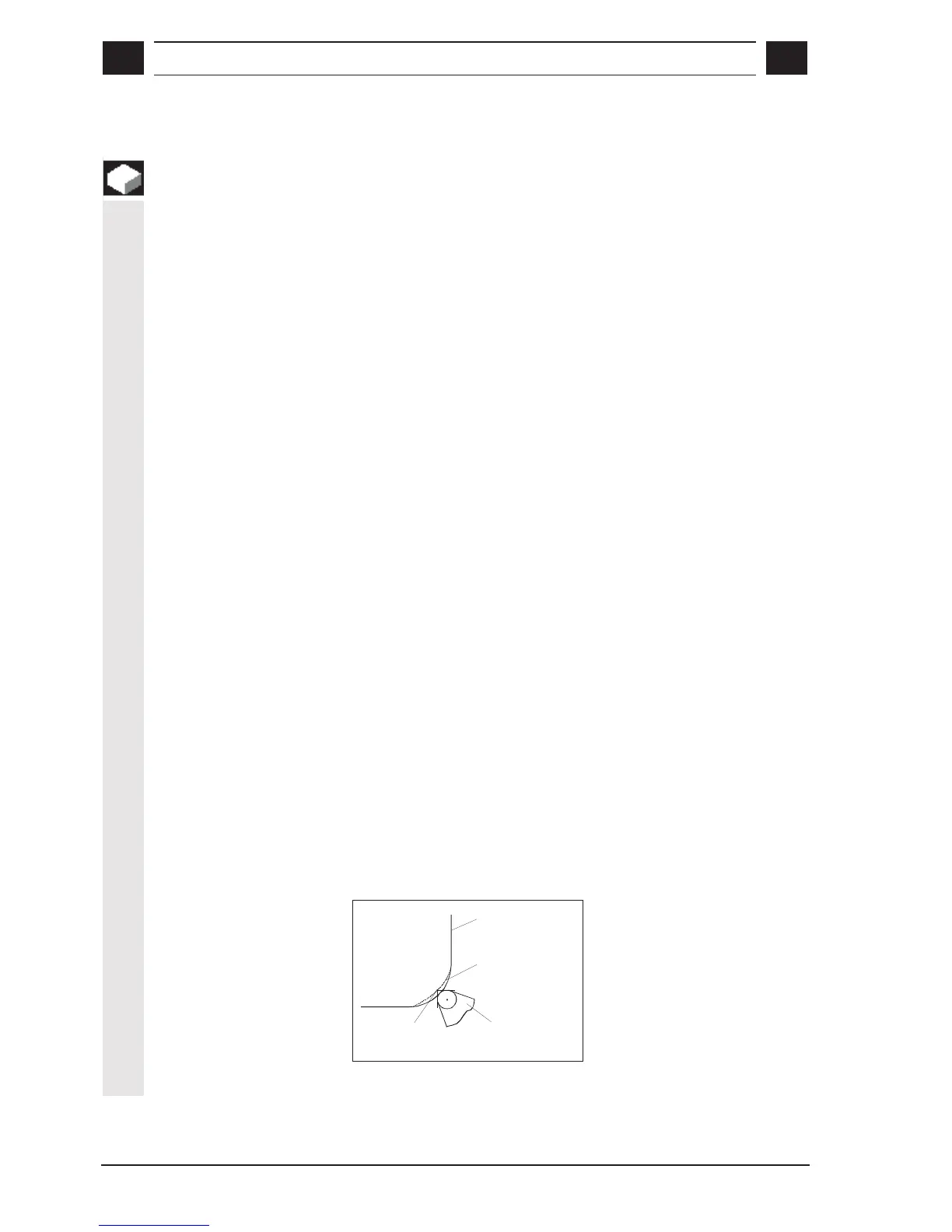
The graphic display of the tool path may differ from the real tool path
on the machine during roughing of inside or outside corners (with or
without rounding).
Roughing is always performed without tool nose radius compensation.
The broken-line graphics show the tool path during corner machining
at the corner of the tool nose.
Contour
Tool path when
roughing
Corner of the
tool nose
Cutting edge

 Loading...


