stem
2
© Siemens AG, 2002. All rights reserved
2-38 SINUMERIK 840D/810D Operator's Guide ManualTurn (BAM) – 08.02 Edition
2.5.7 Tool and cutting data
The main tool and cutting data are as follows:
• Tool T
• Feedrate F
• Spindle speed S or pitch P
Parameter input field With the exception of the parameter P for the thread lead (only in the
"Thread" cycle), the above mentioned parameters are displayed in the
parameter input fields with all turning cycles (in MANUAL, STRAIGHT,
CONICAL, CIRCLE, CYCLE, MACHINING and CONTOUR modes).
Display window
The display windows for tool, feed and spindle speed showing the
current information about the machine state are located underneath
the actual-value display.
These are defined with the following address letters and units in the
parameter input field.
T
Set this parameter to define the tool that you wish to use for the
respective turning cycle.
If you change the tools on your machine manually, you must enter the
number of the required tool from the tool table.
Example: Select tool 2 from the table
If you machine is equipped with a turret and tools are changed
automatically, you must enter a 3 or 4 digit number. The first 1 or 2
digits correspond to the turret number and the last two digits to the
number of the tool from the tool table. You must always enter the tool
number as a 2-digit number.
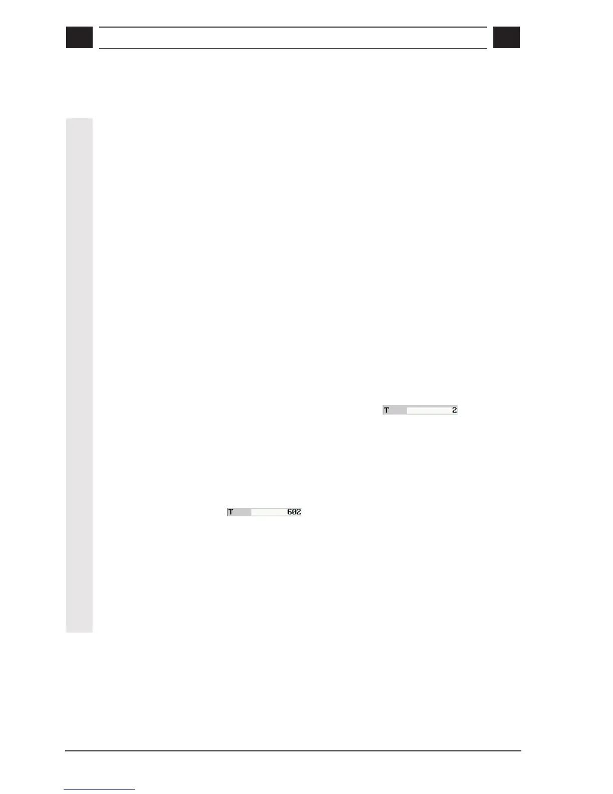
Example: Select tool 2 from the table in turret location 6
With the STRAIGHT, CONICAL and CIRCLE modes, tool selection is
modal, that is, if several cycles with the same tool occur in sequence,
it is necessary to program a tool for the 1st cycle only. The T field in
the input screens for the following cycles remains empty.
The currently active tool (as tool number) and the tool point direction
(as symbol) are displayed in the tool window.

 Loading...


