hics interface
2
© Siemens AG, 2002. All rights reserved
SINUMERIK 840D/810D Operator's Guide ManualTurn (BAM) – 08.02 Edition 2-27
2.4 Graphics interface
Screen layout
1
2
19
18
17
16
15
14
13
12
11
10
9
8
7
6
4
3
5
Explanation of display
elements
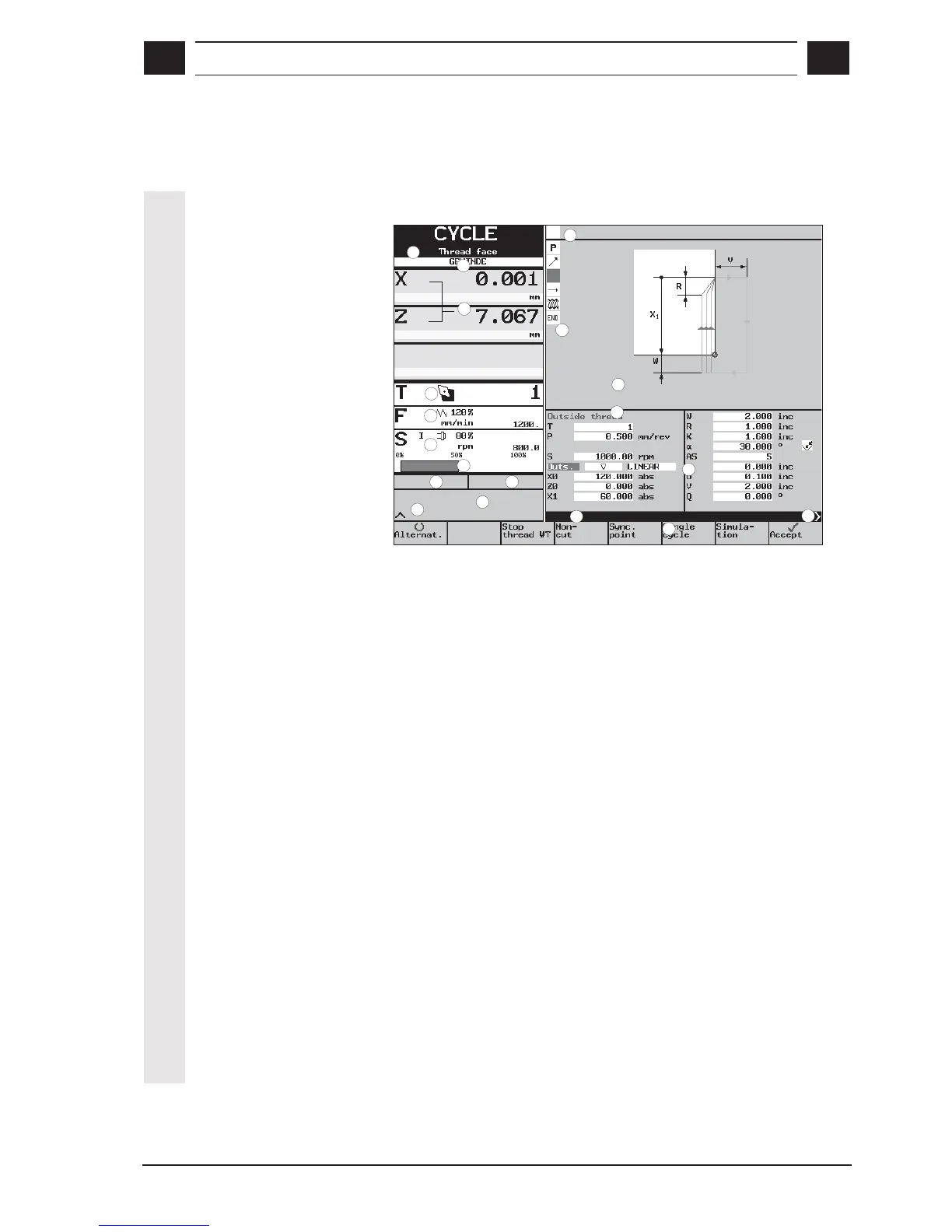
1 Name of the operating modes:
MANUAL, STRAIGHT, TAPER, CIRCLE, CYCLE, STOCK
REMOVAL, CONTOUR, PROGRAM
together with any applicable submenu; applies to CYCLES and
CONTOUR only (e.g. Thread face, Undercut, Stock removal)
2 Position displays
3 Feed display
4 Speed display with rotational direction
5 Output display
6 Tool data
• Tool number
• Tool position
7 Status field:
This field contains the following information depending on the
current machining situation:
• Test run
• TNRC left, TNRC right (TNRC=tool nose radius compensation)
• Dwell
• Ack aux. command (acknowledge auxiliary command)
• Travel command
• Manual offs. (manual offset)
• Current zero offset
• Data trans. (data transmission)

 Loading...


