Fundamental Geometrical Principles
1.4 Axes
Fundamentals
Programming Manual, 10.2004 Edition, 6FC5 298-7AB00-0BP1
1-29
$
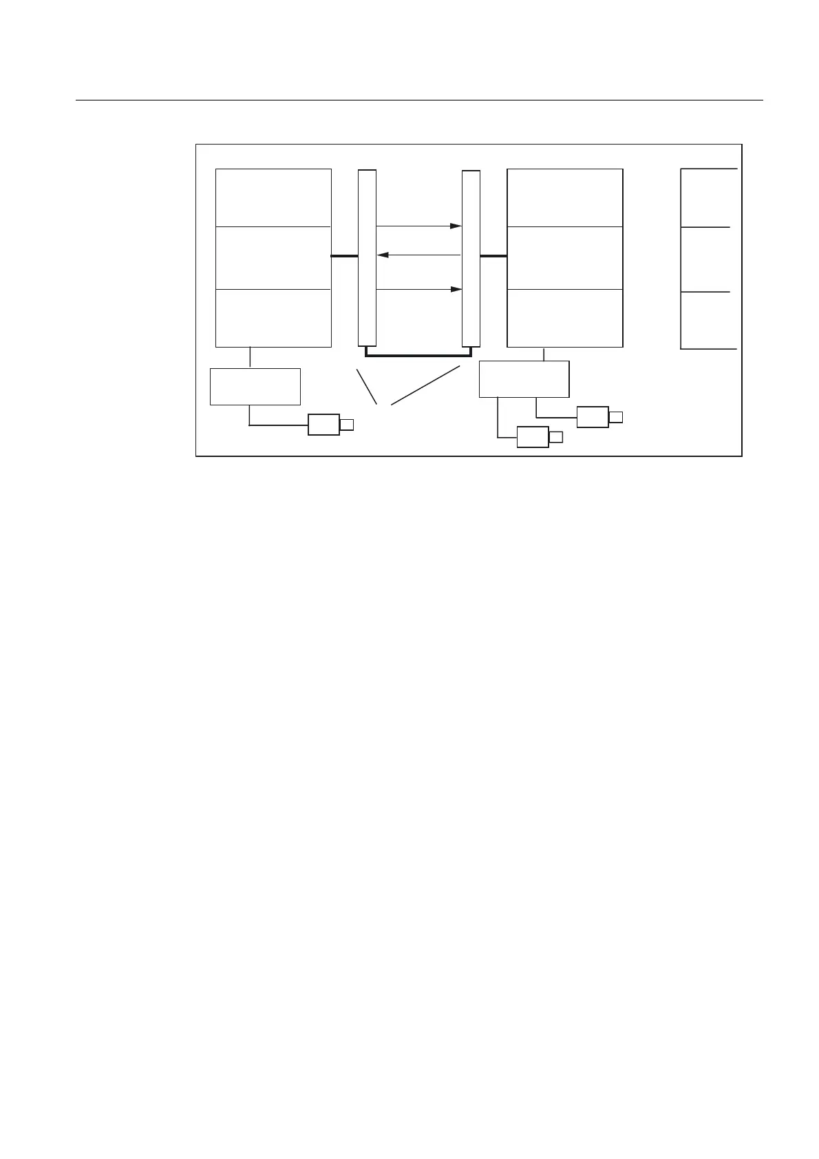
1&8
,QWHUSRODWRU
6HUYR
'
%
%
'
1&8
,QWHUSRODWRU
6HUYR
1&8OLQNPRGXOH
6HWSRLQWVIURP$
&KDQQHOFRQWURO
E\IROORZLQJ
D[LVD[HV
$FWXDOYDOXHV
IURP$
1&8Q
An axial position controller alarm is sent to all other NCUs, which are connected to the
affected axis via a leading link axis.
NCUs that are dependent on the leading link axis can utilize the following coupling
relationships with it:
• Master value (setpoint, actual master value, simulated master value)
• Coupled motion
• Tangential correction
• Electronic gear (ELG)
• Synchronous spindle
Programming
Master NCU:
Only the NCU, which is physically assigned to the master value axis can program travel
motions for this axis. The travel program must not contain any special functions or
operations.
NCUs of slave axes:
The travel program on the NCUs of the slave axes must not contain any travel commands for
the leading link axis (master value axis). Any violation of this rule triggers an alarm.
The leading link axis is addressed in the usual way via channel axis identifiers. The states of
the leading link axis can be accessed by means of selected system variables.
Prerequisites
• The dependent NCUs, i.e., NCU1 to NCUn (n equals, max. of 8), must be interconnected
via the link module for high-speed communication.
References:
/PHD/, Configuring Manual NCU 571-573.2, Link Module
 Loading...


