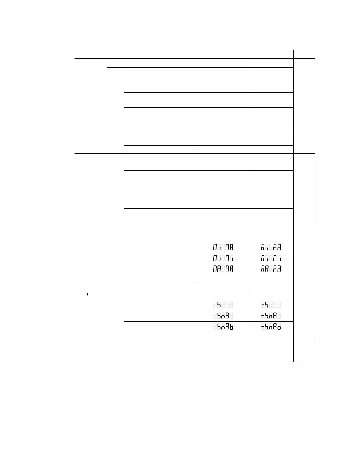
Parameter Function Parameter values Unit
42.BIN1
2)
Digital input function DI1 NO contact NC contact
None OFF
Message only on -on
Block configuration bLoc1
Block configuring and manual
operation
bLoc2
Move process valve to YE po‐
sition
uP -uP
Move process valve to YA po‐
sition
doWn -doWn
Block movement StoP -StoP
Partial Stroke Test PSt -PSt
43.BIN2
2)
Digital input function DI2 NO contact NC contact
None OFF
Message only on -on
Move process valve to YE po‐
sition
uP -uP
Move process valve to YA po‐
sition
doWn -doWn
Block movement StoP -StoP
Partial stroke test PSt -PSt
44.AFCT
3)
Alarm function Normal Inverted
None OFF
A1 = Min, A2 = Max
A1 = Min, A2 = Min
A1 = Max, A2 = Max
45.A1 Response threshold, alarm 1 0.0 ... 10.0 ... 100.0 %
46.A2 Response threshold, alarm 2 0.0 ... 90.0 ... 100.0 %
47. FCT
3)
Function for fault message output Normal Inverted
Fault
Fault + not automatic
4)
Fault + not automatic + DI
4)
48. TIM Monitoring period for setting of fault
message 'Control deviation'
Auto / 0 ... 100 s
49. LIM Response threshold of fault message
'Control deviation'
Auto / 0 ... 100 %
Parameter assignment
8.3 Tabular overview of the parameters
SIPART PS2 with 4 to 20 mA/HART
138 Operating Instructions, 11/2019, A5E00074631-AE

 Loading...


