[lo-uespg-u2-gegsys-20101108, 1, en_US]
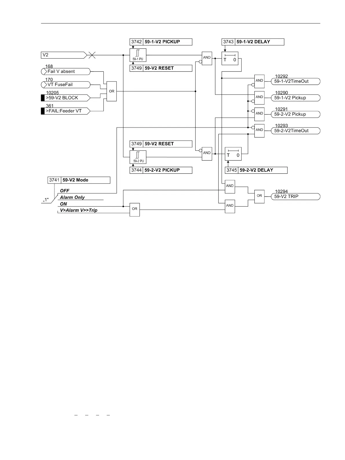
Figure 2-48
Logic diagram of the overvoltage protection for the negative sequence voltage system V
2
The overvoltage protection for the negative sequence system can also be blocked via a binary input
>59-V2
BLOCK
. The elements of the negative sequence voltage protection are automatically blocked as soon as an
asymmetrical voltage failure is detected („fuse failure monitor“, also see Section 2.14.1 Measurement Supervi-
sion, margin heading Rapid Measuring Voltage Failure “Fuse-Failure-Monitor”) or when tripping of the MCB for
voltage transformers has been signaled via the binary input
>FAIL:Feeder VT
(internal indication “internal
blocking”).
Overvoltage Zero Sequence System 3V
0
Figure 2-49 depicts the logic diagram of the zero sequence voltage element. The fundamental frequency is
numerically filtered from the measuring voltage so that the harmonics or transient voltage peaks remain
largely harmless.
The triple zero sequence voltage 3·V
0
is fed to the two threshold elements 59G-1-3V0PICKUP (address
3722) and 59G-2-3V0PICKUP (address 3724). Combined with the associated time delays 59G-1-3V0
DELAY (address 3723) and 59G-2-3V0 DELAY (address 3725) these elements form a two-element over-
voltage protection for the zero sequence system. Here too, the dropout ratio can be set (59G RESET), address
3729). Furthermore, a restraint delay can be configured which is implemented by repeated measuring
(approx. 3 periods).
The overvoltage protection for the zero sequence system can also be blocked via a binary input
>59-3V0
BLOCK
. The elements of the zero sequence voltage protection are automatically blocked as soon as an asym-
metrical voltage failure was detected (“Fuse-Failure-Monitor”, also see Section 2.14.1 Measurement Supervi-
sion, margin heading “Fuse-Failure-Monitor (Non-symmetrical Voltages)” or when the trip of the mcb for
voltage transformers has been signaled via the binary input
>FAIL:Feeder VT
(internal indication “internal
blocking”).
According to Figure 2-49 the device calculates the voltage to be monitored
3·
V
0
= V
A
+ V
B
+ V
C
.
Functions
2.8 Undervoltage and Overvoltage Protection (optional) 27/59
SIPROTEC 4, 7SD80, Manual 111
E50417-G1100-C474-A2, Edition 02.2018

 Loading...


