Overvoltage Positive Sequence System V
1
The device calculates the positive sequence system according to its defining equation
V
1
=
1
/
3
·(V
A
+ a·V
B
+ a
2
·V
C
)
where a = e
j120°
.
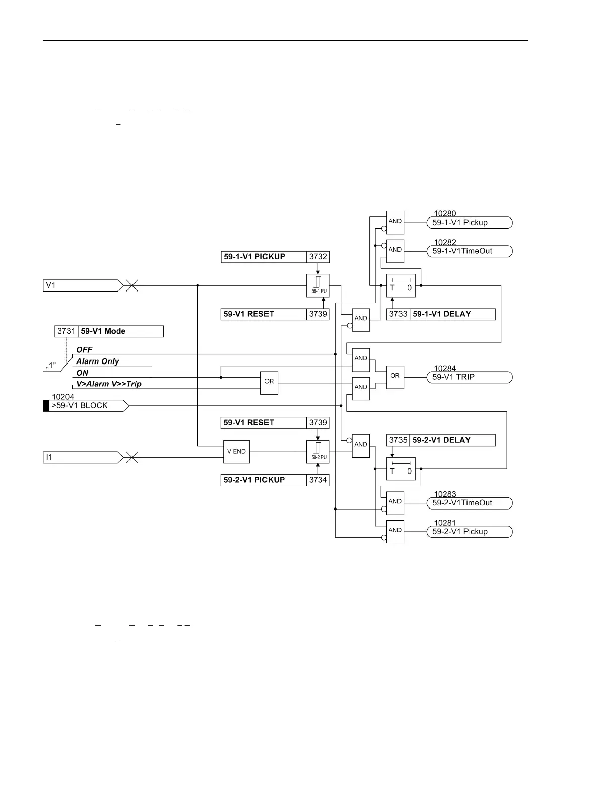
The resulting positive sequence voltage is fed to the two threshold elements 59-1-V1 PICKUP (address
3732) and 59-2-V1 PICKUP (address 3734) (see Figure 2-47). Combined with the associated time delays
59-1-V1 DELAY (address 3733) and 59-2-V1 DELAY (address 3735) these elements form a two-element
overvoltage protection for the positive sequence system. Here too, the dropout ratio can be set.
The overvoltage protection for the positive sequence system can also be blocked via a binary input
>59-V1
BLOCK
.
[lo-uespg-mitsys-20101108, 1, en_US]
Figure 2-47
Logic diagram of the overvoltage protection for the positive sequence voltage system
Overvoltage Negative Sequence System V
2
The device calculates the negative sequence system voltages according to its defining equation:
V
2
=
1
/
3
·(V
A
+ a
2
·V
B
+ a·V
C
)
where a = e
j120°
.
The resulting negative sequence voltage is fed to the two threshold elements 59-1-V2 PICKUP (address
3742) and 59-2-V2 PICKUP (address 3744). Figure 2-48 shows the logic diagram. Combined with the asso-
ciated time delays 59-1-V2 DELAY (address 3743) and 59-2-V2 DELAY (address 3745) these elements
form a two-element overvoltage protection for the negative sequence system. Here too, the dropout ratio can
be set.
Functions
2.8 Undervoltage and Overvoltage Protection (optional) 27/59
110 SIPROTEC 4, 7SD80, Manual
E50417-G1100-C474-A2, Edition 02.2018

 Loading...


