condition, dropout of the signal
VT FuseFail
can no longer be accomplished by the increase of the zero
sequence current or negative sequence current, but only by the voltages in the zero sequence and negative
sequence system falling below a threshold value. The signal
VT FuseFail
can also be generated independ-
ently of the magnitude of the phase currents.
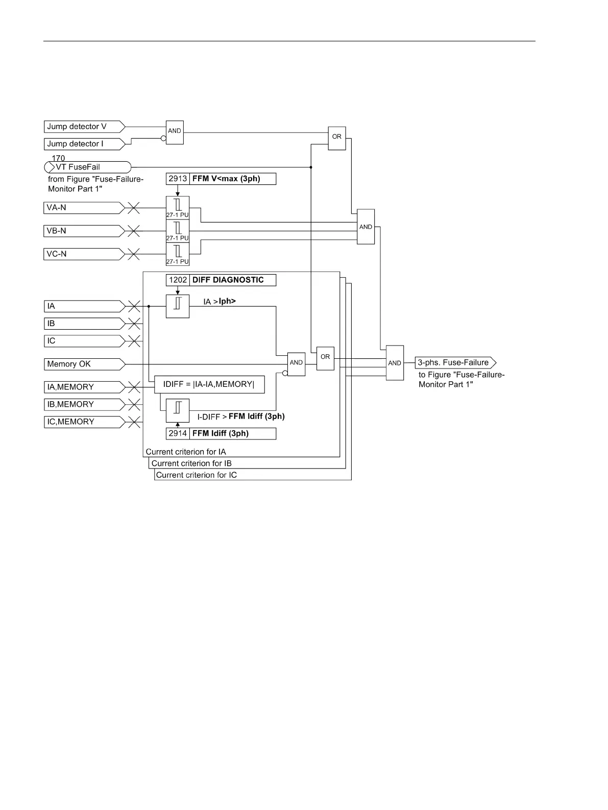
[lo-ffm-mcl-02-20101014, 1, en_US]
Figure 2-70
Fuse Failure Monitor part 2: detection of the 3-phase measuring voltage failure
A 3-phase failure of the secondary measuring voltages can be distinguished from an actual system fault by
the fact that the currents have no significant change in the event of a failure in the secondary measured
voltage. For this reason, the current values are routed to a buffer so that the difference between present and
stored current values can be analyzed to recognize the magnitude of the current differential (current differen-
tial criterion), cf. Figure 2-70.
A 3-pole measuring voltage failure is detected if:
•
All 3 phase-to-ground voltages assume a value smaller than the threshold value FFM V<max (3ph)
(address 2913).
•
The current differential in all 3 phases is smaller than the threshold value FFM Idiff (3ph) (address
2914).
If such a voltage failure is recognized, the protection functions that operate on the basis of undervoltage are
blocked until the voltage failure is removed; afterwards the blocking is automatically removed. The definite
time overcurrent protection as emergency function is possible during voltage failure, provided that the time
overcurrent protection is parameterized accordingly (see 2.4 Backup overcurrent).
A 3-pole measuring voltage failure is also detected in the absence of these criteria if the signal
VT FuseFail
(no. 170) was previously generated due to an unbalanced measuring voltage failure. In this condition, meas-
uring voltage failure is still detected if the 3 phase-to-ground voltage subsequently falls below the threshold
value FFM V<max (3ph) (address 2913).
Functions
2.14 Monitoring Functions
156 SIPROTEC 4, 7SD80, Manual
E50417-G1100-C474-A2, Edition 02.2018

 Loading...


