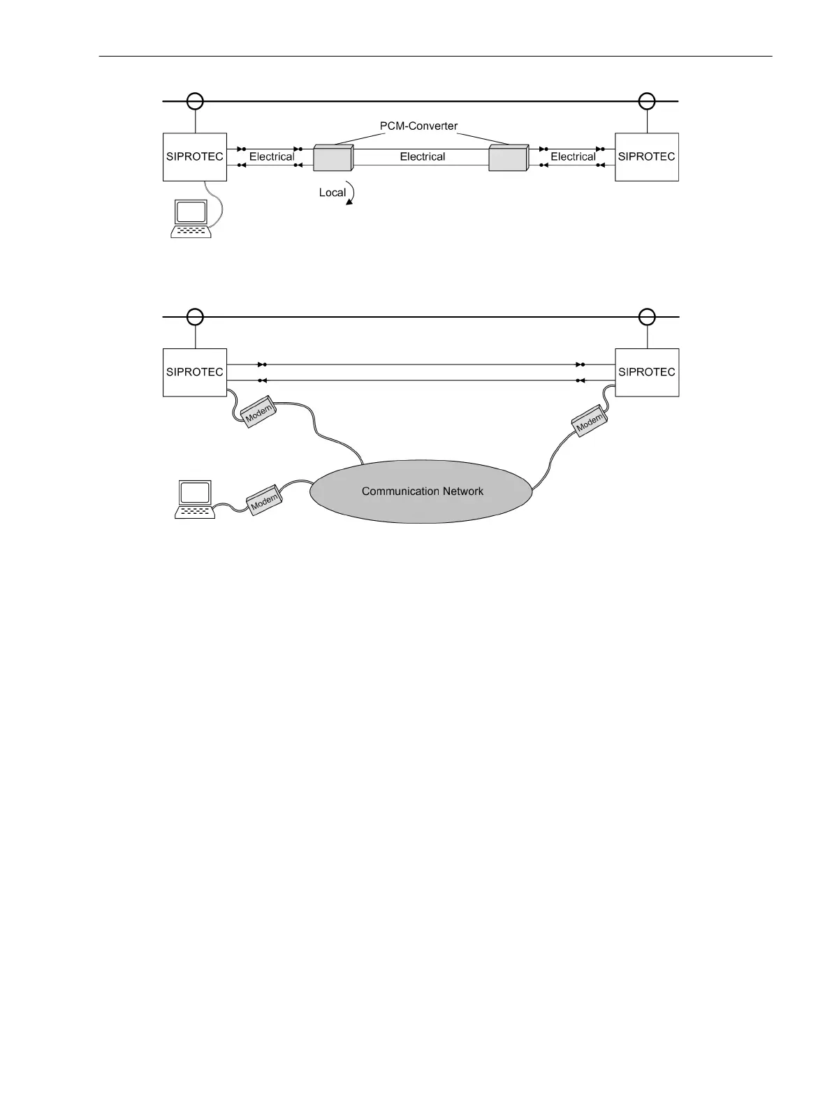
[topologie-kommunikationsnetz-20110120, 1, en_US]
Figure 3-28 Direct connection of the PC to the device using the CU protection data interface – basic
example
[topologie-ankopplung-pc-modem-240702-kn, 1, en_US]
Figure 3-29 Connection of the PC via modem - basic example
Checking a Connection Using Direct Link
In case of an optical fiber link (as shown in Figure 3-27 or Figure 3-29) or via copper conductor link, this
connection is checked as follows:
•
Both devices at the link ends have to be switched on.
•
Check in the event log or in the spontaneous annunciations:
–
If the message
PDI FO con. to.
(protection data interface connected with no. 3243) is provided
with the device index of the other device in case of an optical fiber conductor, a link has been estab-
lished and one device has recognized the other.
–
If the message
PDI Cu con. to.
(protection data interface connected with no. 3244) is provided
with the device index of the other device in case of a copper connection, a link has been established
and one device has recognized the other.
–
The device indicates
Slave Login
, no. 3492 or
Master Login
, no. 3491 if the other device has
been detected.
•
In case of an incorrect communication link, the indication
PDI FO faulty
(no. 3230) or
PDI Cu
faulty
(no. 3232) is displayed. In this case, check the connection again:
– Are the connections correct and not swapped?
– Are the cables free from mechanical damage, intact and the connectors locked?
– Otherwise repeat the verification.
Continue with the margin heading “Consistency of Connection and Parameterization”.
Consistency of Connection and Parameterization
Having performed the above checks, the linking of a device pair has been completely tested and connected to
auxiliary supply voltage. Now the devices contact each other on their own account.
Mounting and Commissioning
3.3 Commissioning
SIPROTEC 4, 7SD80, Manual 237
E50417-G1100-C474-A2, Edition 02.2018

 Loading...


