[dw_first and second device row, 1, en_US]
Figure 6-11
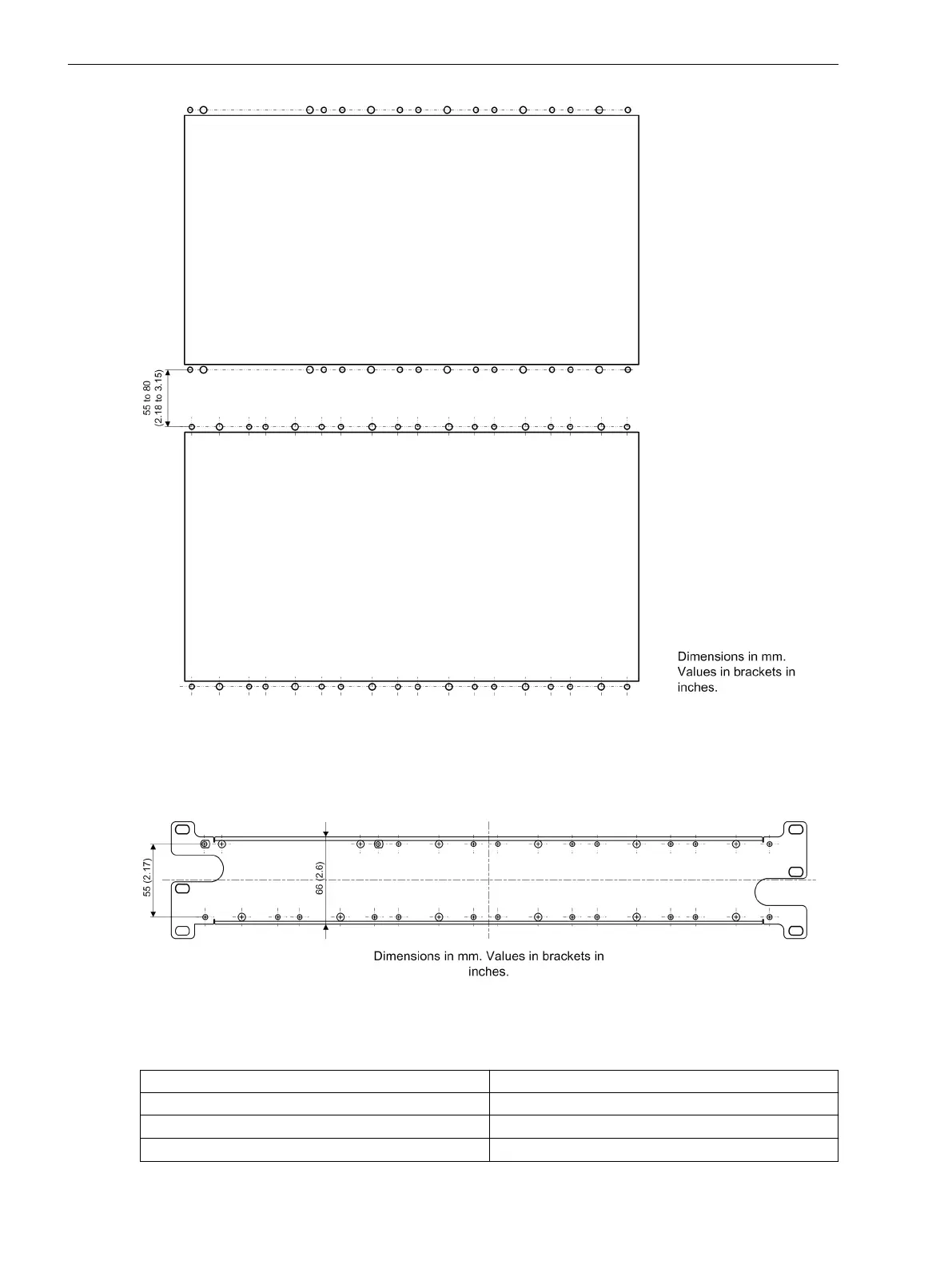
Drilling Pattern – 1/1 Devices, 1st and 2nd Device Row
Siemens recommends a drilling space of at least 55 mm (2.17 in) between the 1st and 2nd device row. Due to
the connecting-cable length, the maximum space may be approx. 80 mm (3.15 in). The length of the cable is
890 mm (35.04 in) from the center of the plug to the center of the plug.
[dw_angle rail, 1, en_US]
Figure 6-12 Angle Rail for Connection of the 1st and 2nd Device Row
Table 6-7 Cut-Out Widths
Width of the Assembly Opening in mm (in Inches)
1/3 device (base module)
146
+2
mm (5.75
+0.08
)
1/2 device (base module with one expansion module)
221
+2
mm (8.7
+0.08
)
2/3 device (base module with 2 expansion modules)
296
+2
mm (11.65
+0.08
)
Technical Data
6.14 Assembly Dimensions
254 SIPROTEC 5, Hardware Description, Manual
C53000-G5040-C002-J, Edition 08.2020

 Loading...


