2.9 Backup Time Overcurrent Protection
105
7SD610 Manual
C53000-G1176-C145-4
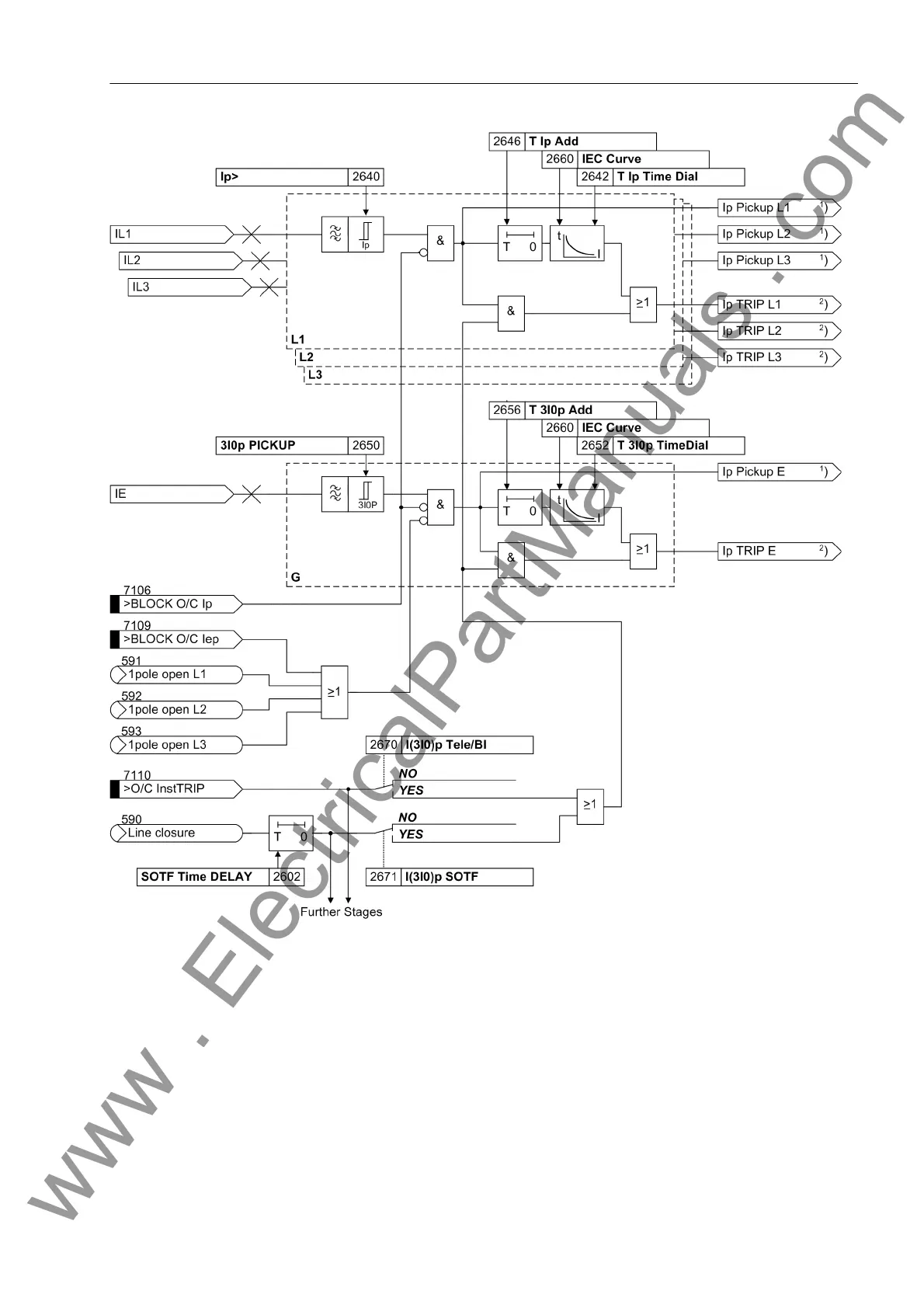
Figure 2-41 Logic diagram of the I
P
stage (inverse time overcurrent protection) - example of IEC curve
1
) Output indications associated with the pickup signals are listed in Table 2-3
2
) Output indications associated with the trip signals are listed in Table 2-4
Directional inverse
time overcurrent
stage I
P
ger
The logic of the directional inverse overcurrent stage operates chiefly in the same way
as the non-directional stages. However, triggering is not dependent on the result of the
direction determination. Direction determination occurs via the measuring values and
the respective directional characteristics.
However, the time delay is calculated here based on the type of the set characteristic,
the intensity of the current and a time multiplier D Ip Dir. or D 3I0p Dir.. Fur-
thermore, an additional constant time delay T Ip Add Dir. or T 3I0p Add Dir.
www . ElectricalPartManuals . com

 Loading...


