2.15 Monitoring Functions
199
7SD610 Manual
C53000-G1176-C145-4
Sampling Frequen-
cy
The sampling frequency and the synchronism between the ADCs (analog-to-digital
converters) is continuously monitored. If deviations cannot be corrected by another
synchronisation, the device sets itself out of operation and the red „Blocked“ LED
lights up; The Device OK relay drops off and signals the malfunction by its „life con-
tact“.
Measured Value
Capturing Currents
There are four measurement inputs in the current paths. If the three phase currents
and the earth current from the current transformer starpoint or a separated earth
current transformer of the line to be protected are connected to the device, their digi-
tised sum must be zero. A fault in the current circuit is detected when
I
F
= |I
L1
+ I
L2
+ I
L3
+ k
I
·I
E
| > ΣI THRESHOLD·I
N
+ ΣI FACTOR·Σ | I |
Factor k
I
(address 221 I4/Iph CT) takes into account a possible different ratio of a
separate I
E
transformer (e.g. cable core balance current transformer). ΣI THRESHOLD
and ΣI FACTOR. are setting parameters.
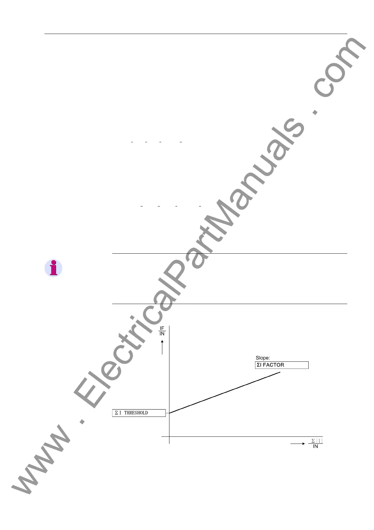
The component ΣI FACTOR Σ | I | takes into account permissible current proportional
ratio errors of the input transformers which are particularly prevalent during large fault
currents (Figure 2-80). Σ | I | is the sum of all currents:
Σ | I | = |I
L1
| + |I
L2
| + |I
L3
| + |k
I
·I
E
|
As soon as a summation current fault is detected after or before a system disturbance,
the differential protection is blocked. This malfunction is signalled as „Failure Σi“
(No. 289). In order to avoid a blocking due to transformation errors (saturation) in case
of high fault currents, this monitoring function is not effective during a system fault.
Note
Current sum monitoring can operate properly only when the ground current of the pro-
tected line is fed to the fourth current measuring input (I
4
) of the relay. The I
4
trans-
former must have been configured with parameter I4 transformer (address 220)
as In prot. line.
Figure 2-80 Current sum monitoring
www . ElectricalPartManuals . com

 Loading...


