2.15 Monitoring Functions
201
7SD610 Manual
C53000-G1176-C145-4
After a settable time (5-100 s) this malfunction is signaled as „Fail I balance“
(no. 163).
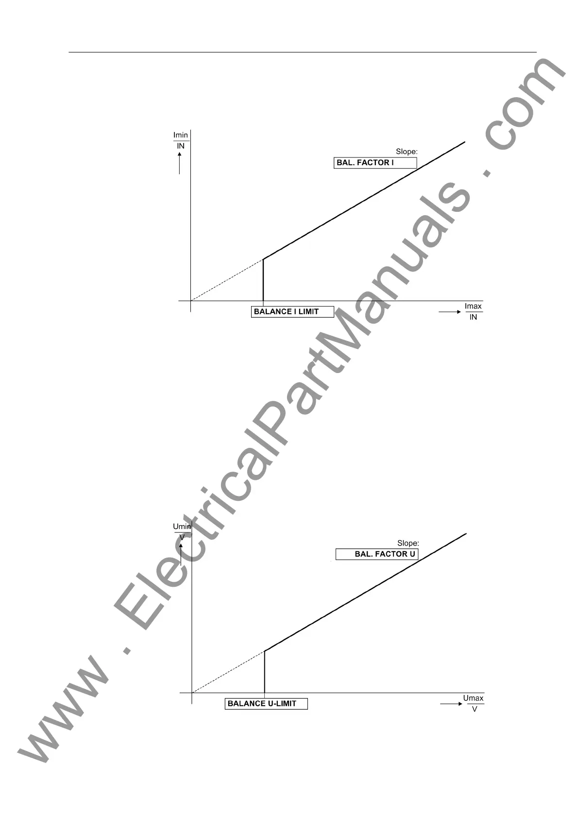
Figure 2-81 Current symmetry monitoring
Voltage Symmetry In healthy network operation it can be expected that the voltages are nearly balanced.
The monitoring of the measured values in the device checks this balance. The small-
est phase voltage is compared to the largest. Non-symmetry is detected when
|U
min
| / | U
max
| < BAL. FACTOR U as long as | U
max
| > BALANCE U-LIMIT
U
max
is the largest of the three phase-to-phase voltages and U
min
the smallest. The
symmetry factor BAL. FACTOR U (address 2903) represents the allowable asymme-
try of the voltages while the limit value BALANCE U-LIMIT (address 2902) is the
lower limit of the operating range of this monitoring (see Figure 2-82). The dropout
ratio is about 97%.
After a settable time, this malfunction is signaled as „Fail U balance“ (no. 167).
Figure 2-82 Voltage symmetry monitoring
www . ElectricalPartManuals . com

 Loading...


