2 Functions
54
7SD610 Manual
C53000-G1176-C145-4
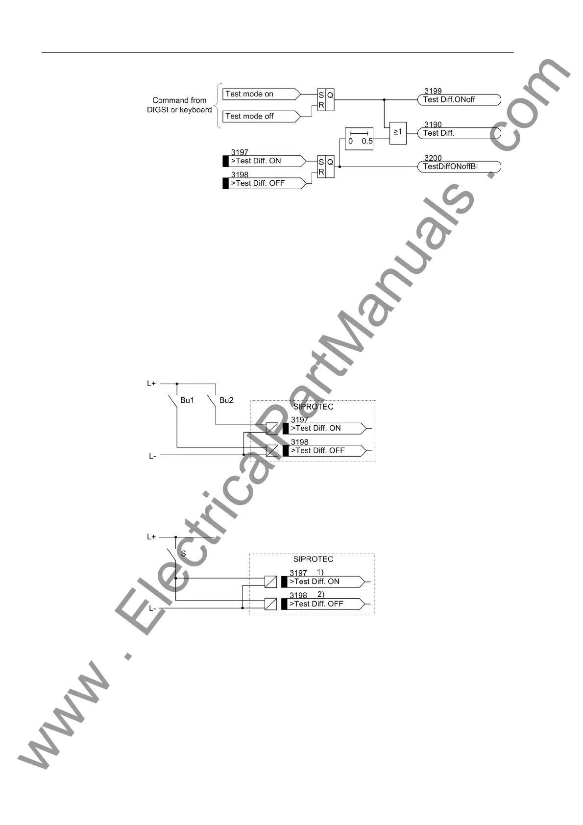
Figure 2-8 Logic diagram of the test mode
Depending on the way used for controlling the test mode, either the indication „Test
Diff.ONoff“ (No. 3199) or „TestDiffONoffBI“ (No. 3200) is generated. The
way used for deactivating the test mode always has to be identical to the way used for
activating. The indication „Test Diff.“ (No. 3190) is generated independently of
the chosen way. When deactivating the test mode via the binary inputs, a delay time
of 500 ms becomes effective.
The following figures show possible variants for controlling the binary inputs. If a
switch is used for the control (Figure 2-10), it has to be observed that binary input
„>Test Diff. ON“ (No. 3197) is parameterised as NO contact and that binary input
„>Test Diff. OFF“ (No. 3198) is parameterised as NC contact.
Figure 2-9 External button wiring for controlling the differential protection test mode
Bu1 Button „Deactivating differential protection test mode“
Bu2 Button „Activating differential protection test mode“
Figure 2-10 External switch wiring for controlling the differential protection test mode
S Switch „Activating/deactivating differential protection test mode“
1) Binary input as NO contact
2) Binary input as NC contact
www . ElectricalPartManuals . com

 Loading...


