2 Functions
64
7SD610 Manual
C53000-G1176-C145-4
The secondary currents which are applied to the devices via the current transformers,
are subject to measuring errors caused by the response characteristic of the current
transformers and the input circuits of the devices. Transmission errors such as signal
jitters can also cause deviations of the measured quantities. As a result of all these
influences, the total sum of all currents processed in the devices in healthy operation
is not exactly zero. Therefore, the differential protection is restrained against these in-
fluences.
Charging Currents Due to the capacitances of the three phases against ground and against one another,
charging currents are flowing even in healthy operation and cause a difference of cur-
rents at the ends of the protected zone. Especially when cables are used, the capac-
itive charging currents can reach considerable magnitude.
Charging currents do not depend on the intensity of the measured currents. In healthy
operation they can be considered as being almost constant under steady-state condi-
tions, since they are only determined by the voltage and the capacitances of the lines.
They can therefore be taken into account during the setting of the sensitivity of the dif-
ferential protection (see also Subsection 2.3.2 under „Pickup Value of Differential Cur-
rent“). The same is true for the steady-state magnetizing currents across shunt reac-
tances. The devices have a separate inrush restraint feature for transient inrush
currents (see below under the margin heading „Inrush Restraint“).
Current
transformer errors
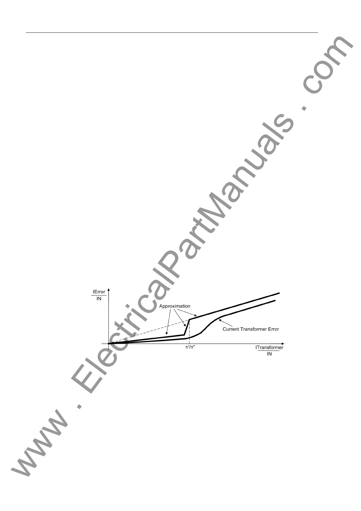
To consider the influences of current transformer errors, each device calculates a self-
restraining quantity I
error
. This is calculated by estimating the possible local transform-
er errors from the data of the local current transformers and the intensity of the locally
measured currents (see Figure 2-17). The current transformer data have been param-
eterized in the power system data (Section 2.1.2.1 under margin heading „Current
Transformer Characteristic“ and apply to each individual device. Since each device
transmits its estimated errors to the other devices, each device is capable to form the
total sum of possible errors; this sum is used for restraint.
Figure 2-17 Approximation of the current transformer errors
Further influences Further measuring errors which may arise in the actual device by hardware toleranc-
es, calculation tolerances, deviations in time or due to the „quality“ of the measured
quantities such as harmonics and deviations in frequency are also estimated by the
device and automatically increase the local self-restraining quantity. Here, the permis-
sible variations in the data transmission and processing periods are also considered.
Deviations in time are caused by residual errors during the synchronization of mea-
sured quantities, data transmission and operating time variations, and similar events.
When GPS synchronization is used, these influences are eliminated and do not in-
crease the self-restraining quantity.
www . ElectricalPartManuals . com

 Loading...


