2 Functions
66
7SD610 Manual
C53000-G1176-C145-4
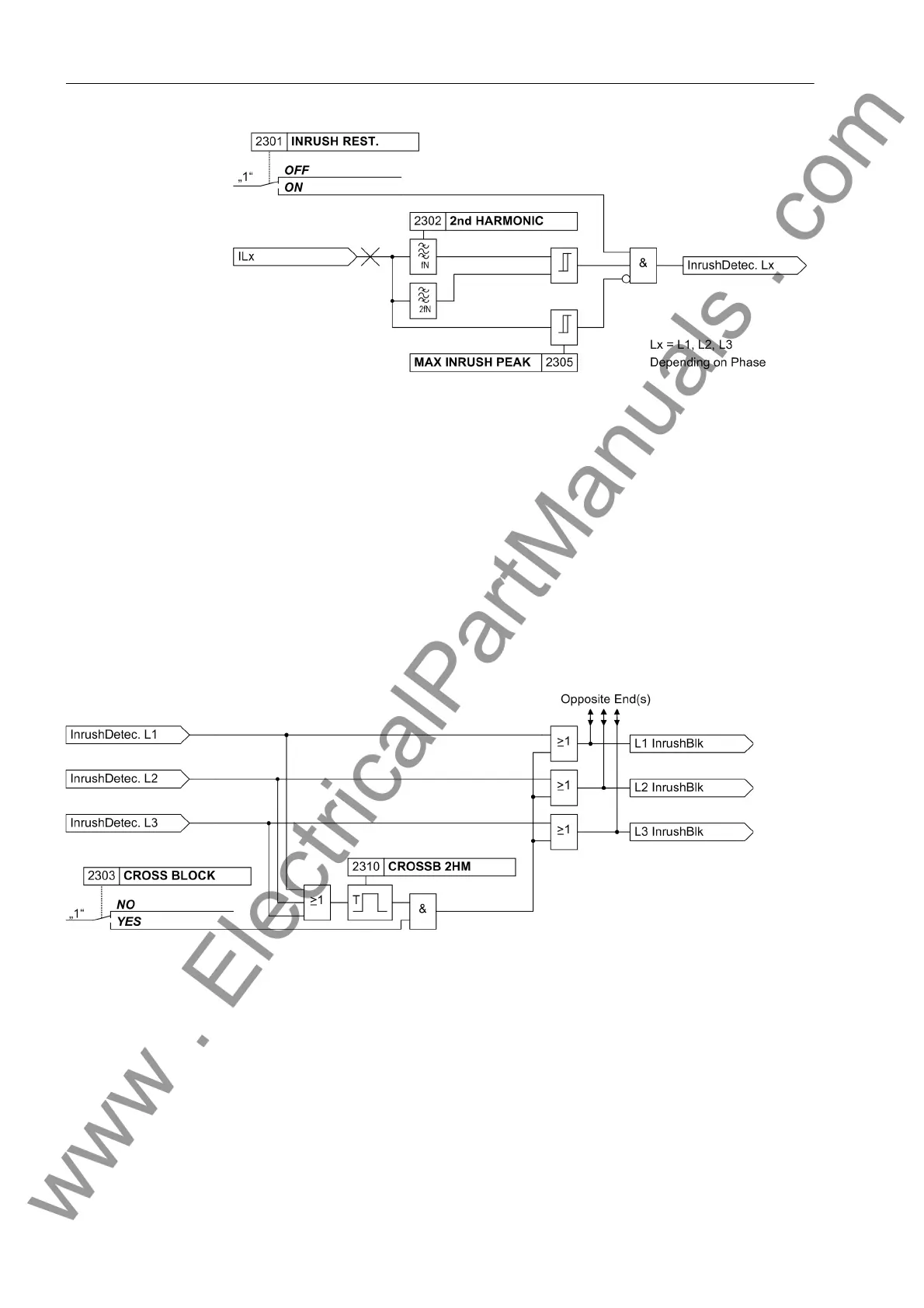
Figure 2-18 Logic diagram of the inrush restraint for one phase
Since the inrush restraint operates individually for each phase, the protection is fully
operative when the transformer is switched onto a single-phase fault, whereby an
inrush current may possibly flow through one of the undisturbed phases. It is, however,
also possible to set the protection in such a way that when the permissible harmonic
content in the current of only one single phase is exceeded, not only the phase with
the inrush current but also the remaining phases of the differential stage are blocked.
This cross-block function can be limited to a selectable duration. Figure 2-19 shows
the logic diagram.
The cross-block function also affects both devices since it not only extends the inrush
restraint to all three phases but also sends it to the other device via the communication
link.
Figure 2-19 Logic diagram of the cross-block function for one end
Evaluation of the
measured
quantities
The evaluation of measured values is performed separately for each phase. Addition-
ally, the residual current is evaluated.
Each device calculates a differential current from the total of the current phasors that
were formed at each end of the protected zone and transmitted to the other ends. The
differential current value is equal to the value of the fault current that is registered by
the differential protection system. In the ideal case it is equal to the fault current value.
In a healthy system the differential current value is low and similar to the charging cur-
rent.
www . ElectricalPartManuals . com

 Loading...


