'(& )( )'& &) ( &!& ")& &$(( $# Ć %&( $# #)" &&#$
6 - 50
Siemens AG ⋅ May 1998
L+
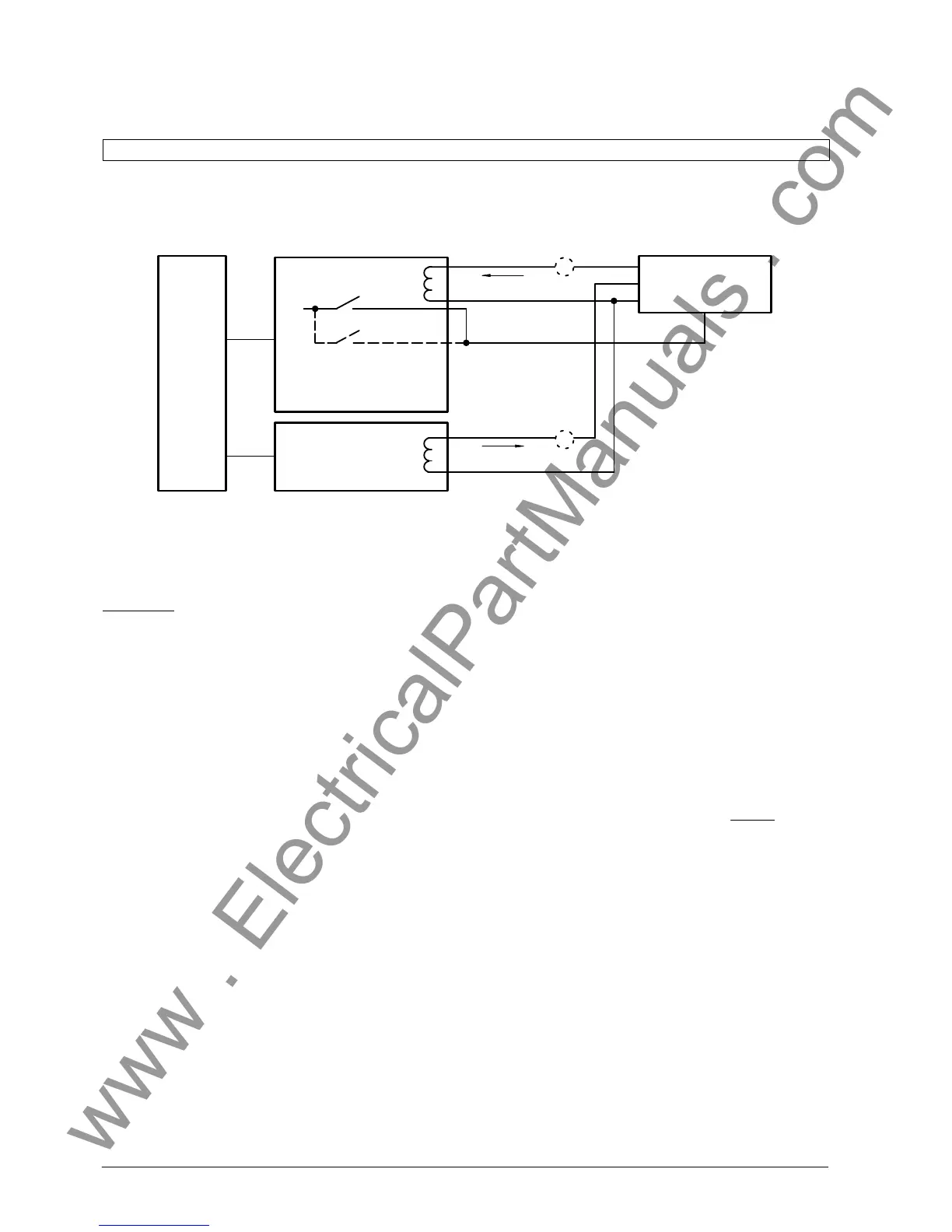
A
A
Alarm Diff.Super-
vision (BB section
or check zone)*
Test set
(e. g. 7VP15)
Bay unit 2
Bay unit 1
TRIP
Test current I
2
Test current I
1
Master
unit
FO
FO
* for testing diff-current limit for suĆ
pervisory function (refer to chapter
6.5.3)
Test steps:
1. Test currents I
1
and I
2
must have a phase differĆ
ence of 180_. To check the phase angle, an identiĆ
cal current (0.5 I
N
) is injected through feeder 1 and
feeder 2 from the test set.
With the correct phase angle and connection, the
diff-current must amount to almost zero and the
stabilizing current must be 2 x the test current. If
the differential current is not zero, then the polarity
of the current in one feeder must be reversed.
Display of the differential and stabilizing currents
via the corresponding block addresses 74; 75 and
76.
2. With I
2
= 0, the current I
1
is increased until a trip
signal is initiated. The current in feeder 1 is then
the diff-current limit ( ).
3. A constant current I
1
, which is smaller than the
set diff-current limit, is fed into feeder 1 from the
test set. The current I
2
in feeder 2 is slowly inĆ
creased until the protection picks up.
Differential current is then I =II
1
+ I
2
I and the
stabilizing current I I I=II
1
I+II
2
I.
Stabilizing factor k = I/ I I I=II1+I2I/
(I I1I+II2I)
4. For the characteristic I I
2
- I
1
I=k[II
1
I+II
2
I]
Since I
1
and I
2
have a phase angle difference of
180_ the following is obtained
I
2
(1-k)=I
1
(1 + k) resp. I
2
Ă +Ă I
1
Ă
1Ă )Ăk
1Ă ćĂ k
with k = 0.8 it follows that I
2
=9I
1
5. The test is repeated with different constant curĆ
rents I
1
(correct shape of the characteristic is given
in Fig 6.4).
 Loading...


