'(& )( )'& &) ( &!& ")& &$(( $# Ć %&( $# #)" &&#$
4 - 33
Siemens AG ⋅ May 1998
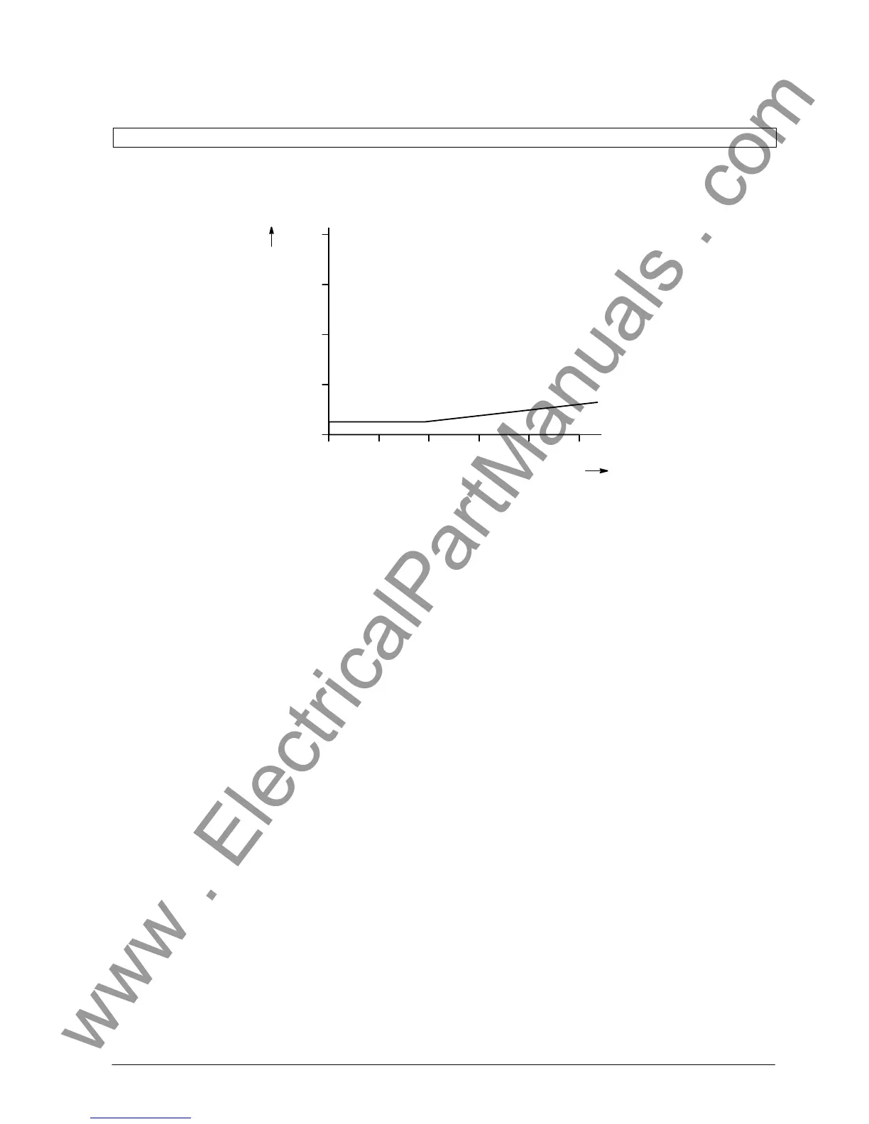
0 0.25 0.5 0.75 1.0
0.25
0.5
0.75
1.0
Fault current
DI / I
n
Stabilizing current S |āāāIāāā|/I
n
Error in measured values
I > DIFF.
k
No error in measured values
If the supervision detects that the measured values
are not plausible, then the analogue measuring cirĆ
cuits are considered faulty, the measured value cycle
is accordingly marked and the measurement for that
cycle is blocked. If the fault prevails for a longer time,
it is annunciated.
D Memory (FE and ZE)
The memory modules are cyclicly tested for faults by
the following measures:
- A checksum is formed for the program memory
(Flash-EPROM) during start-up and cyclicly.
- For the working memory (RAM), a data pattern is
written during start-up and read again.
- For the parameter and configuration data memory
(EEPROM), the checksum of the stored quantities
is formed and compared with the checksum calcuĆ
lated during each new writing process.
- For the dual-port RAM on the slave modules, the
stored parameters are compared with the data on
the master module.
D Output trip channels (FE)
The output trip channels are controlled via two comĆ
mand channels and one release channel. Checking of
the signal output channels is performed in connection
with the cyclic protection test (refer 4.7.8.8).
Watchdog timers are provided on the processor modĆ
ules to continuously monitor the program sequences.
In the event of processor failure or if a program falls
out of step the watchdog operates and initiates a reĆ
set of the processor system.
Further internal plausibility checks and program seĆ
quence monitoring ensure that any fault in processing
of the programs will be detected. Such faults also
lead to a reset and restart of the processor.
If a fault is not eliminated by restarting, a further reĆ
start is initiated. If the fault is still present after three
restart attempts, the protection system is automatiĆ
cally taken out of service. The ready-for-service relay
on the alarm module (EAZ1) drops off and indicates
"Equipment failure" via its NC contact.
The LED "failure" on the frontplate of the master unit
or the affected bay unit lights up red.
 Loading...


