'(& )( )'& &) ( &!& ")& &$(( $# Ć %&( $# #)" &&#$
5 - 3
Siemens AG ⋅ May 1998
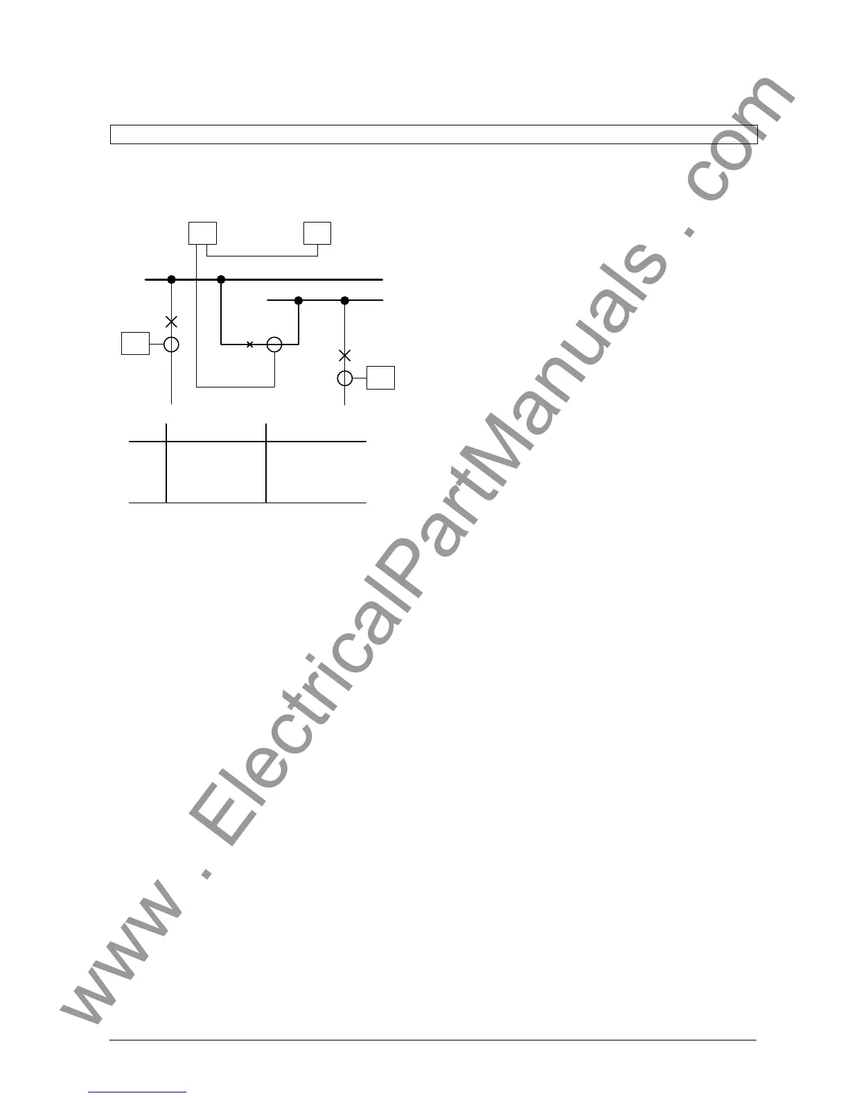
BBB
FE2FE1
CPBBA
BBA
FE4
FE3
FE Direct address Setting
1
2
3
4
0105
0205
0305
0405
line-side
busbar-side
line-side
line-side
D Open both inscription strips in the front cover, maĆ
king accessible 4 elongated holes.
D Insert unit into the panel cutout or cubicle mounĆ
ting frame and fix with four screws (dimension
drawings are shown in chapter 2.6.1).
D Connect earthing screw at the unit's rear side with
the protection earth of the panel or cubicle.
D A solid low-ohmic and low-inductive operating
earth has to be connected to the earthing point of
the casings rear wall using at least one screw M4.
Earth tapes according to DIN 72333 form A are
suitable for this.
D Make electrical connections via the snap-in or
screw-type connection modules of the unit. SpeĆ
cial care has to be paid to the designations of the
snap-in connection modules.
D The fibre-optical connection is carried out by
means of FSMA screw connections.
D The subrack with degree of protection IP 20 is suiĆ
table for mounting in panels and cubicles.
D It is fixed from the front side by at least four
screws. Make sure that the fixing flanges at both
sides fully contact the surface (dimension draĆ
wings are shown in chapter 2.6.2).
D Connect earthing terminal on the casing's outside
(refer to Fig 2.7) with the protection earth of the
panel or cubicle.
D A solid low-ohmic and low-inductive operating
earth via the earthing terminal is essential.
D Make electrical connections via the snap-in or
screw-type connection modules of the unit. For
the connection of the optical signals fibre-optical
cables with pre-fabricated FSMA plugs are used.
The FO cables have to connected in the sequence
of the programmmed bay units. The marking syĆ
stem at the device's rear side supports the conĆ
nection.
D For installation attention has to be paid to secure
fixing of the cubicle to the floor.
D The cubicle must be solidly earthed low-ohmic
and low-inductive. Earthing must be done by
using the screw-type connection of the cubicle
which is marked with the earthing symbol. In case
of more than one cubicle, all cubicles must be conĆ
nected solidly low-ohmic with each other.

 Loading...


