'(& )( )'& &) ( &!& ")& &$(( $# Ć %&( $# #)" &&#$
4 - 12
Siemens AG ⋅ May 1998
Busbar protection via the check zone comprises all
bays (with the exception of the bus coupler) regardĆ
less of isolator status. In some special cases, isolator
status must however be considered for the check
zone. If the stabilizing current is calculated in the
same manner as for the bus-section specific busbar
protection, overstabilization results in multiple busbar
systems since the bays which are not connected to
the faulty busbar strongly stabilize the protection.
Therefore, the stabilizing current is calculated as folĆ
lows:
S | I
p
| = sum of the magnitudes of the currents
which flow in the direction of the busbar
S I I
n
I = sum of the magnitudes of the currents
which flow away from the busbar
I
Stab
= lesser of the above two sums.
By forming the stabilizing current in this manner, only
half of the total through-flowing load current acts as
stabilizing current.
The short-circuit current does not stabilize the "check
zone" and only acts as differential current.
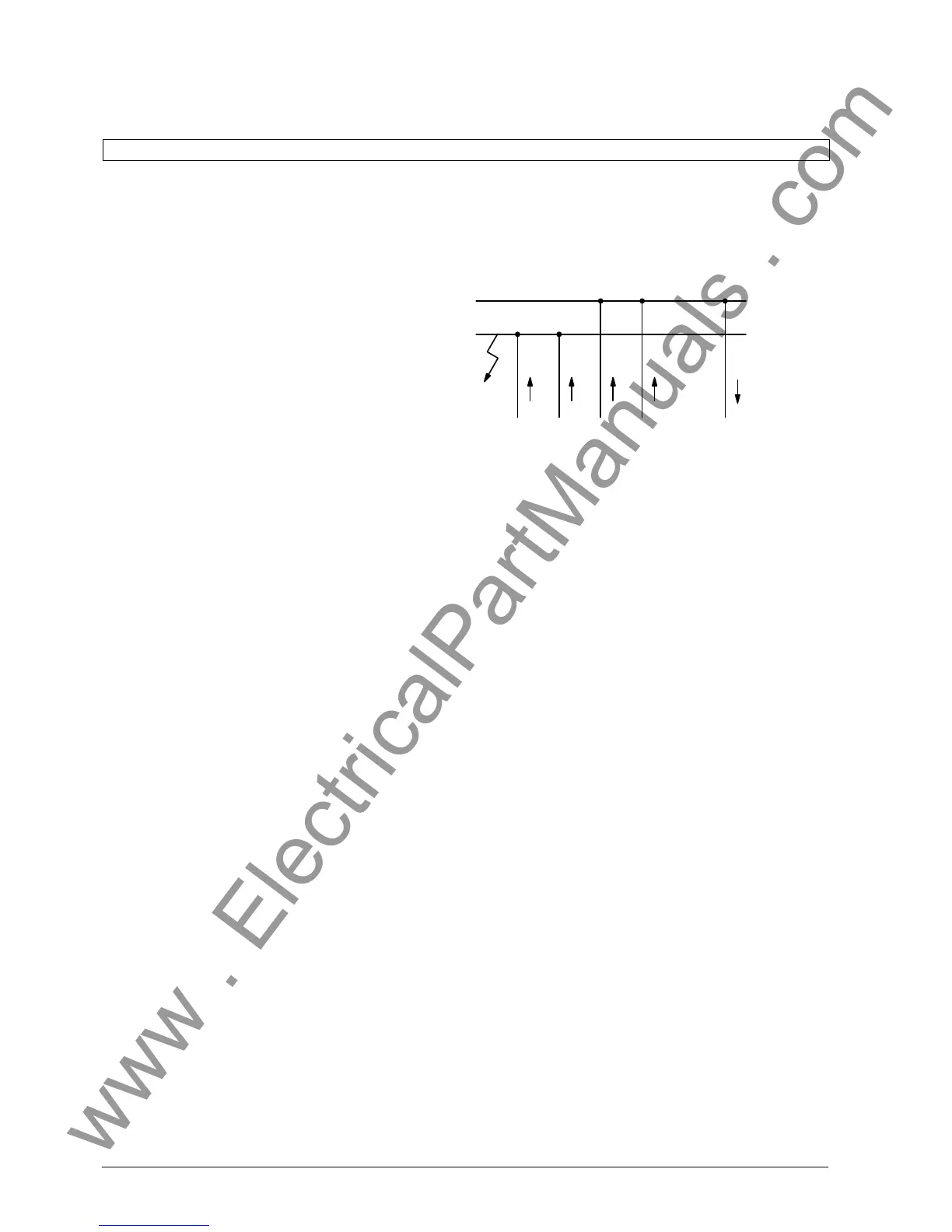
This procedure is illustrated in Fig 4.9.
I
1
I
2
I
3
I
3
+ I
4
I
4
BB1
BB2
DI =II
1
+ I
2
+ I
3
+ I
4
- I
3
- I
4
I=II
1
+ I
2
I
Normal stabilizing current without special treatment:
I
Stab
=II1I+II2I+II3I+II4I+II3+I4I.
Load currents I
3
and I
4
are considered twice in the
stabilizing current, which leads to overstabilization.
Special treatment of the stabilizing current results in
the following conditions:
S I I
p
I = I I
1
I+II
2
I+II
3
I+II
4
I
S I I
n
I=II
3
+ I
4
I
I
Stab
= S I I
n
I=II
3
+ I
4
I; is equal to half the mag-
nitude of the load current.
This stabilizing current is modified for evaluation of
the characteristic as mentioned in section 4.3.1.1.
Due to the phase angle differences between short-
circuit current and load currents differences may ocĆ
cur in the formation of the sums.

 Loading...


