'(& )( )'& &) ( &!& ")& &$(( $# Ć %&( $# #)" &&#$
Installation instructions
5
5 - 9
Siemens AG ⋅ May 1998
5.3 Configuration examples
The 7SS52 can be used for protecting busbar confiĆ
gurations with up to 3 main busbars and one transfer
(bypass) busbar or 4 main busbars and up to 48 bays.
For configuration of the up to
D 12 busbar sections (including up to 4 transfer busĆ
bar sections) and
D 12 bus coupler sections
the busbar sections are numbered from left to right
from 1 to 12 and the bus coupler sections from 13 to
24, beginning with the 1st main busbar up to the
transfer busbar or 4th main busbar.
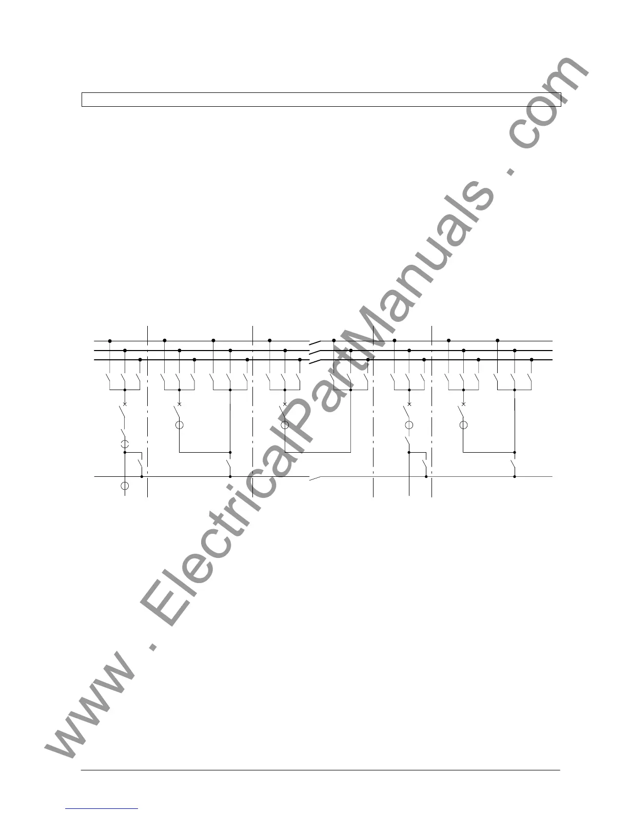
As an example, Fig 5.6 shows the configuration data
for a triple busbar with transfer busbar. For each main
busbar the number of corresponding busbar sections
is parameterized (DA 4900/ZE).
A bus coupler section is a busbar section serving ex-
clusively for coupling busbar sections and containing
no feeders. They normally appear in combiantion with
bus couplers. An example is shown in Fig 5.7.
-Q1 -Q2 -Q3
-Q7
BB1 BZ1
BB2 BZ3
BB3 BZ5
-Q9
-Q2 -Q3
-Q7
-1T
-Q10 -Q20 -Q30
-Q1
-Q2 -Q3
-1T
-Q1 -Q2 -Q3
-Q7
-1T
-Q9
-Q1
-Q2 -Q3
-Q7
-1T
-Q11
-Q31
7
-Q10
-Q20 -Q30
BZ8
-Q10 -Q20 -Q30
BZ2
BZ4
BZ6
-1T
-Q1
-Q71
-Q21
12 3 4 8 569Bay number
BB4 BZ7
2)
1)
Configuration:
DA 5404 BB-ISOLAT4 = TB-Isolator
DA 4900 BB-configuration
DA 4901 BB01/BZ01
DA 4902 BB01/BZ02
DA 4903 BB02/BZ03
DA 4904 BB02/BZ04
DA 4905 BB03/BZ05
DA 4906 BB03/BZ06
DA 4907 BB04/BZ07
DA 4908 BB04/BZ08
1) in-side CT
2) out-side CT
Bay
(XX)
Type of bay Designation ISOL1: Axx
(DA XX07)
ISOL2: Axx
(DA XX08)
ISOL3: Axx
(DA XX09)
ISOL4: Axx
(DA XX10)
ISOL5: AXX
(DA XX11)
CT location
(DA XX04)
01 Coupler 2.1 BZ1 BZ3 BZ5 non existent non existent BB-side
02 Coupler 2.2 BZ1 BZ3 BZ5 BZ7 non existent no CT
03 Coupler 3.1 BZ1 BZ3 BZ5 non existent non existent BB-side
04 Coupler 3.3 BZ2 BZ4 BZ6 non existent non existent no CT
05 Coupler 5.1 BZ2 BZ4 BZ6 non existent non existent BB-side
06 Coupler 5.2 BZ2 BZ4 BZ6 BZ8 non existent no CT
07 Outgoing feeder 1.0 BZ1 BZ3 BZ5 BZ7 existent line-side
08 Outgoing feeder 4.0 BZ2 BZ4 BZ6 BZ8 existent BB-side
09 Sectionalizer 3.2 BZ01/BZ02 BZ03/BZ04 BZ05/BZ06 BZ07/BZ08 non existent no CT
 Loading...


