'(& )( )'& &) ( &!& ")& &$(( $# Ć %&( $# #)" &&#$
7 - 10
Siemens AG ⋅ May 1998
Note to Table 7.5:
The information fields not occupied in the table are of
minor importance for fault analysis or can only be inĆ
terpreted by the manufacturer.
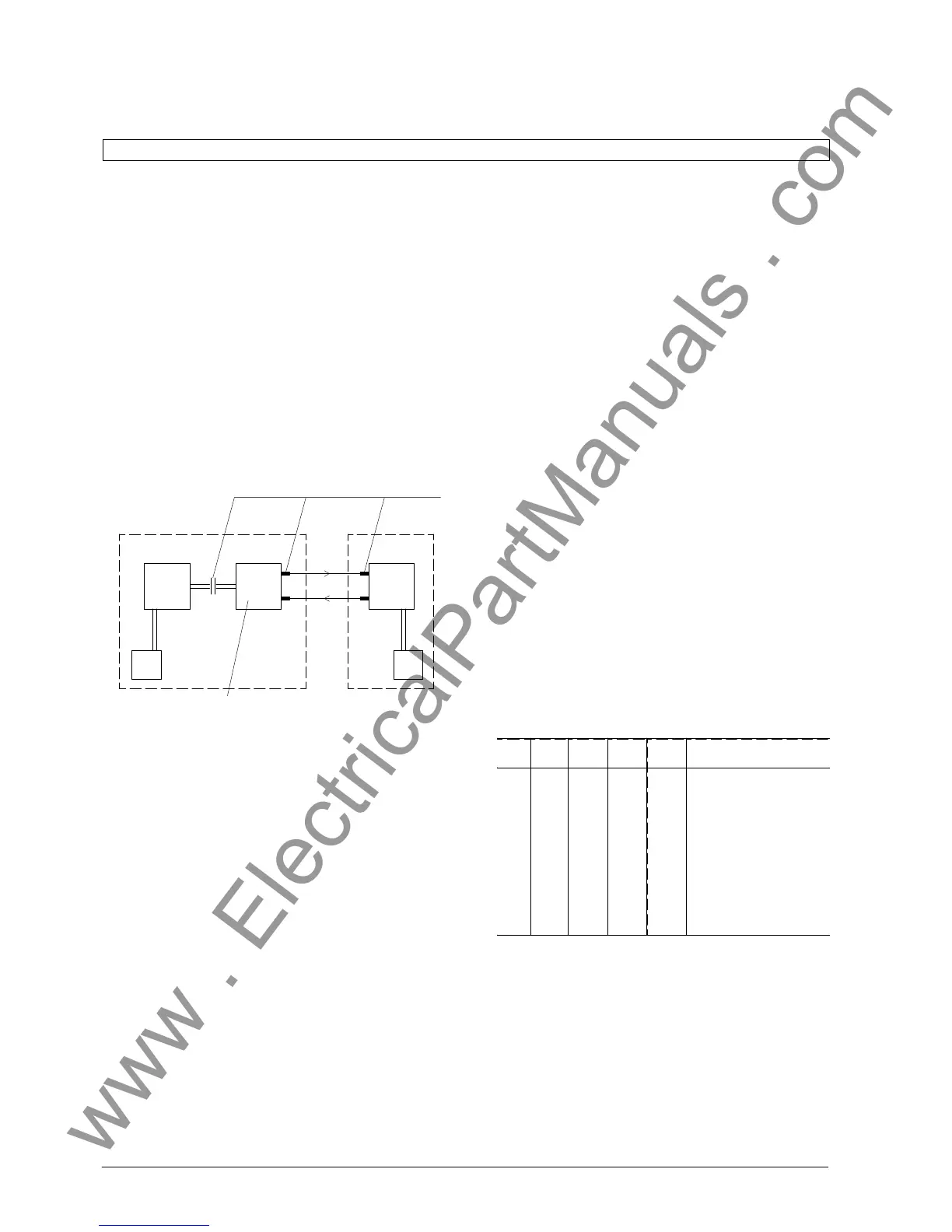
7.2.6 Analysis of failures in the communicaĆ
tion ZE-FE
Following components of the protection participate in
the protection-internal fast data transmission:
ZE
ZPS-
SK
LMZ FE
SVSV
Converter electr./opt.
for 8 channels
Plug connector
FE
Start-up of the master unit can be completed sucĆ
cessfully only if the data links to all configured bay
units can be established without failures.
If only one FE fails, then the protection system is
blocked and a failure alarm is generated.
In the event of failed start-up, indicated by the red
LED "failure", the faulty data link has to be located.
The protection system may continue in service after
the faulty bay was taken out of service. Configuration
"bay out of service" can be done by DA 64xx/ZE.
During the commissioning period or if failures were
detected, the data transmission links have to be teĆ
sted individually. For this procedure a station configuĆ
ration with less bays (e.g. 4) is initially selected.
For this purpose, the 5th bay is configured "non-exiĆ
stent" by parameter DA 0503/ZE. If start-up is comĆ
pleted correctly after switching on the master unit,
then further bays can be configured as "existent",
until the original configuration of the station is reĆ
ached.
It should be noted that the first bay configured as
"non-existent" defines the design of the station.
Failures in data transmission can be located by a speĆ
cific test run.
a) Test run of the ZPS-SK
The FO connection of the concerned channel is
linked by a fibre-optical cable from transmitter to
receiver. Test run can be set by fitting a jumper at
loaction X34 on the ZPS-SK.
The parameter "cyclic protection test" DA
6311/ZE must be switched off for the test run.
The red LED H1 flashes and thus indicates the
test run. The configured bays are checked.
At least one channel must be faulty, if the green
LED H1 (refer to Fig 5.5) flashes. Then the yellow
LEDs indicate the channel with the highest numĆ
ber, which is faulty.
Table 7.6 ZPS-SK
RED
H1
GRN
H1
YELL1
H2
YELL2
H3
YELL3
H4
Status
x
x
x
x
x
x
x
x
+
+
+
+
+
+
+
+
+
-
-
-
-
x
x
x
x
-
-
x
x
-
-
x
x
-
x
-
x
-
x
-
x
Test run ZPS-SK
Failure in channel 1
Failure in channel 2
Failure in channel 3
Failure in channel 4
Failure in channel 5
Failure in channel 6
Failure in channel 7
Failure in channel 8

 Loading...


