'(& )( )'& &) ( &!& ")& &$(( $# Ć %&( $# #)" &&#$
7 - 11
Siemens AG ⋅ May 1998
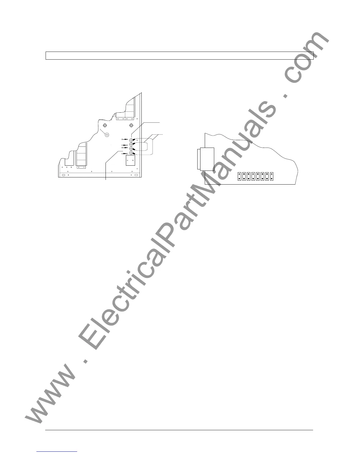
Figure 7.4 Connection of the interface points for
the test run
Connection of the two FO-terminals allows to
check the transmission channel for interruptions
(for max. FO-cable lengths of 700m).
A FO-coupler (part of the delivery) is used to conĆ
nect the FSMA plugs.
After finishing the test, the jumper must be remoĆ
ved and the cyclic protection test must be switĆ
ched on again.
b) Test run of the bay unit
If the test described in a) was run successfully,
then it is very likely that a failure in the bay unit
caused the channel disturbance.
Fitting jumper no 5 on the PFE module activates a
test function (refer to Fig 7.5). The jumper is deliĆ
vered together with the master unit.
The supplementary interface at the bay unit (refer
to Fig 2.5 and 7.4) simulates the master unit for
the test run.
To run the test, the transmitter of the interface to
the master unit is connected to the receiver of the
supplementary interface and the receiver of the
interface to the master unit is connected to the
transmitter of the supplementary interface by a FO
cable (FO cables are delivered together with the
master unit).
In the event of a transmission error in control or
alarm direction, the alarm "Fail com CU"
is issued. This alarm can be allocated
to an LED. After about 0.5 s service without faiĆ
lure, the alarm is cancelled.
PC interface
87654321
Test function "service without master unit"
Fit jumper to location 5
Figure 7.5 Location of jumpers on the module PFE of the
bay unit
Start-up can be completed successfully even with a
failed bay (FE or FO-link defective).
To achieve this, the faulty bay must be taken out of
service. This is done by parameterizing
( ).
The corresponding bay must be excluded from the
protection zone by "isolating".
The protection system allows service of the fault-free
bays until the defective bay unit or FO-cable is replaĆ
ced.

 Loading...


