3RT1/3RH1 contactors
SIRIUS System Manual
3-34
GWA 4NEB 430 0999-02b
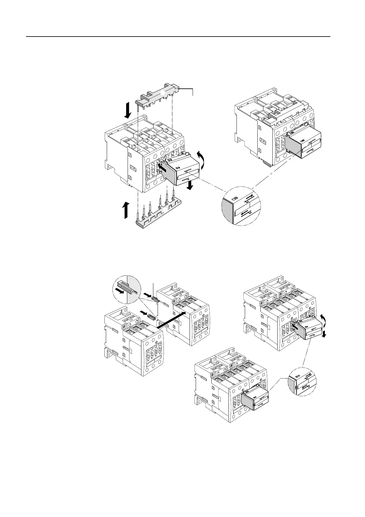
The following graphics show you how to mount the locking devices at the
front for mechanical interlocking in frame size S0:
Figure 3-15: Star-delta combination, locking device at the front (frame size S0)
The following graphics show you how to mount the locking devices at the
front for mechanical interlocking with frame sizes S2 and S3:
Figure 3-16: Star-delta combination, locking devices at the front (frame sizes S2/S3)
The following accessories are components of the self-assembly kits and
they are described in the diagrams of the relevant kit:
• Lateral locking device
• Mechanical connectors
• Wiring modules
1
1
2
3
4
3RA1923-2A
➀
➁
RESET
5
6
1
2
3RA1932-2C
1
2
3
4
5
RESET

 Loading...


