3RT1/3RH1 contactors
SIRIUS System Manual
3-102
GWA 4NEB 430 0999-02b
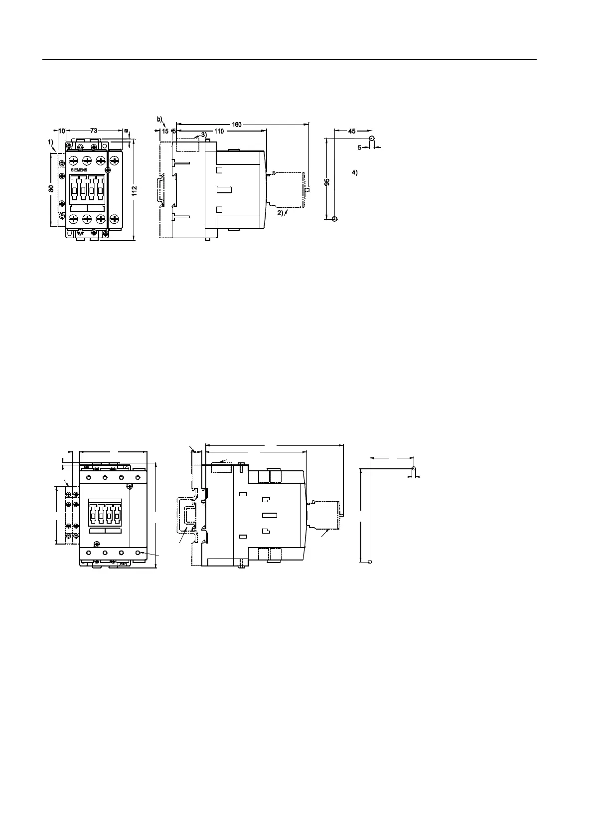
Figure 3-87: 3RT133, 3RT153 (frame size S2)
with surge supressor and auxiliary switch block
a = 0 mm with varistor < 240 V
a = 3.5 mm with varistor > 240 V
a = 17 mm with RC element and diode combination
b = DC 15 mm deeper than AC
1) Auxiliary switch block, attachable at the side (right or left)
2) Auxiliary switch block, attachable at the front, (1-, 2-, and 4-pole, also electronically optimized variant 3RH19 21-1FE22)
3) Surge supressor
4) Drilling pattern
5) Attachment on 35 mm rails (15 mm deep) in acc. with EN 50 022 or 75 mm rails in acc. with EN 50 023
6) 4 mm Allen screw
Distance to grounded parts at the side 6 mm
Figure 3-88: 3RT13 4 (frame size S3)
with surge supressor and auxiliary switch block
a = 0 mm with varistor < 240 V
a = 3.5 mm with varistor > 240 V
a = 17 mm with RC element and diode combination
b = DC 13 mm deeper than AC
1) Auxiliary switch block, attachable at the side (right or left)
2) Auxiliary switch block, attachable at the front, (1-, 2-, and 4-pole, also electronically optimized variant 3RH1921-1FE22)
3) Surge supressor
4) Drilling pattern
5) Attachment on 35 mm rails (15 mm deep) in acc. with EN 50 022 or 75 mm rails in acc. with EN 50 023
6) 4 mm Allen screw
Distance to grounded parts at the side 6 mm
NSB00759c
60
130
5
5
13
134
183
93
146
80
10
a
b
1
5
6
2
4
NSB 00760b
3
SIEMENS

 Loading...


