EasyManua.ls Logo

Siemens SIRIUS - Figure 8-13: 3 RT+3 RW3+3 RB10 Combination; Table 8-12: 3 RT1 + 3 RW30;31 + 3 RB10 Installation Guidelines, Minimum Clearances;Minimum Lengths

Siemens SIRIUS
425 pages
To Next Page IconTo Next Page
To Previous Page IconTo Previous Page
Loading...
3RW3 semiconductor motor control unit
SIRIUS System Manual
GWA 4NEB 430 0999-02b
8-27
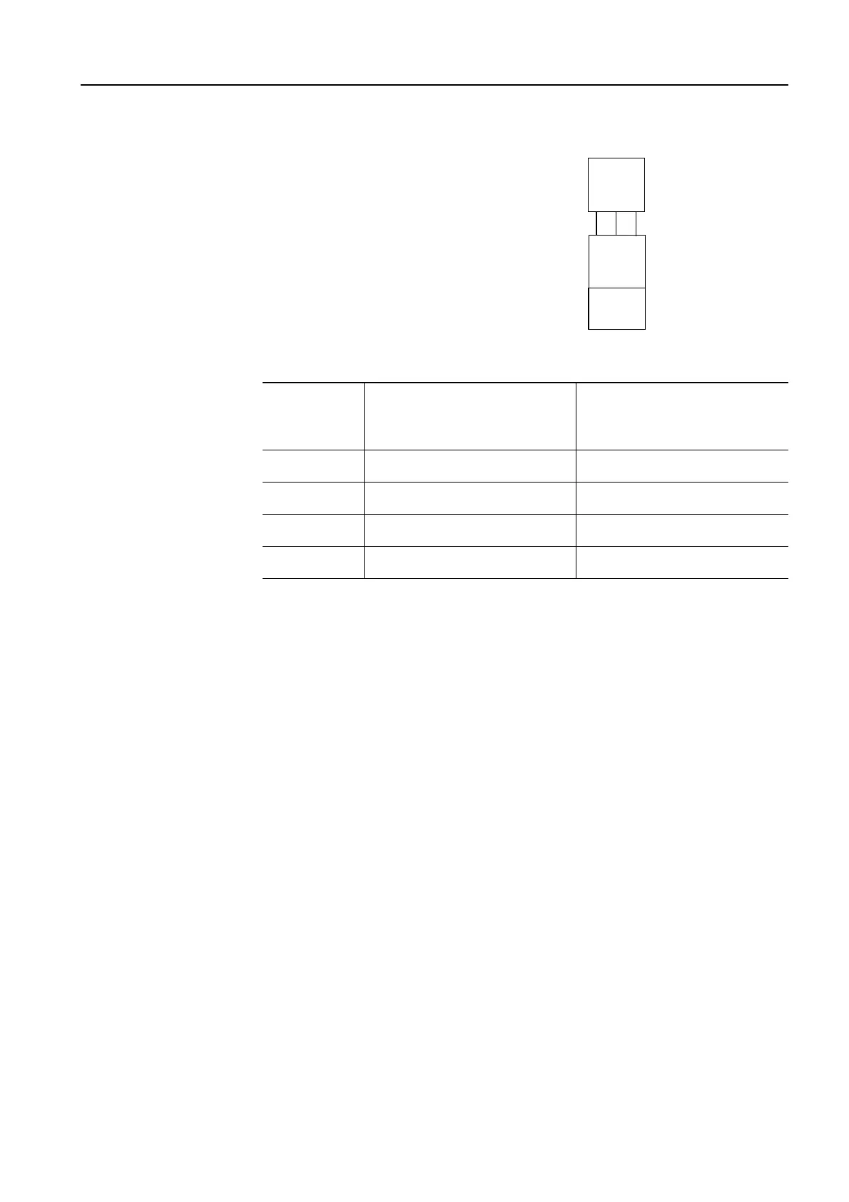
3RT + connecting lead +
3RB10 + 3RW3
Figure 8-13: 3RT+3RW3+3RB10 combination
Minimum clearances
Table 8-12: 3RT1 + 3RW30/31 + 3RB10 installation guidelines, minimum clearances/minimum
lengths
3RT
3RB10
3RW
Rail 1:
3RT1 contactor
Rail 2:
Combination of 3RW30/31 soft
starter and 3RB10 electronic
overload relay
Frame size
Minimum clearance between
rail 1 and rail 2
(center to center) in mm
Minimum length of the
connecting lead
in mm
S00
100 100
S0
140 150
S2
180 200
S3
240 250

Table of Contents

Other manuals for Siemens SIRIUS

Related product manuals