3RU11, 3RB10, and 3RB12 overload relays
SIRIUS System Manual
GWA 4NEB 430 0999-02b
4-19
4.3.2 3RB12 electronic overload relays
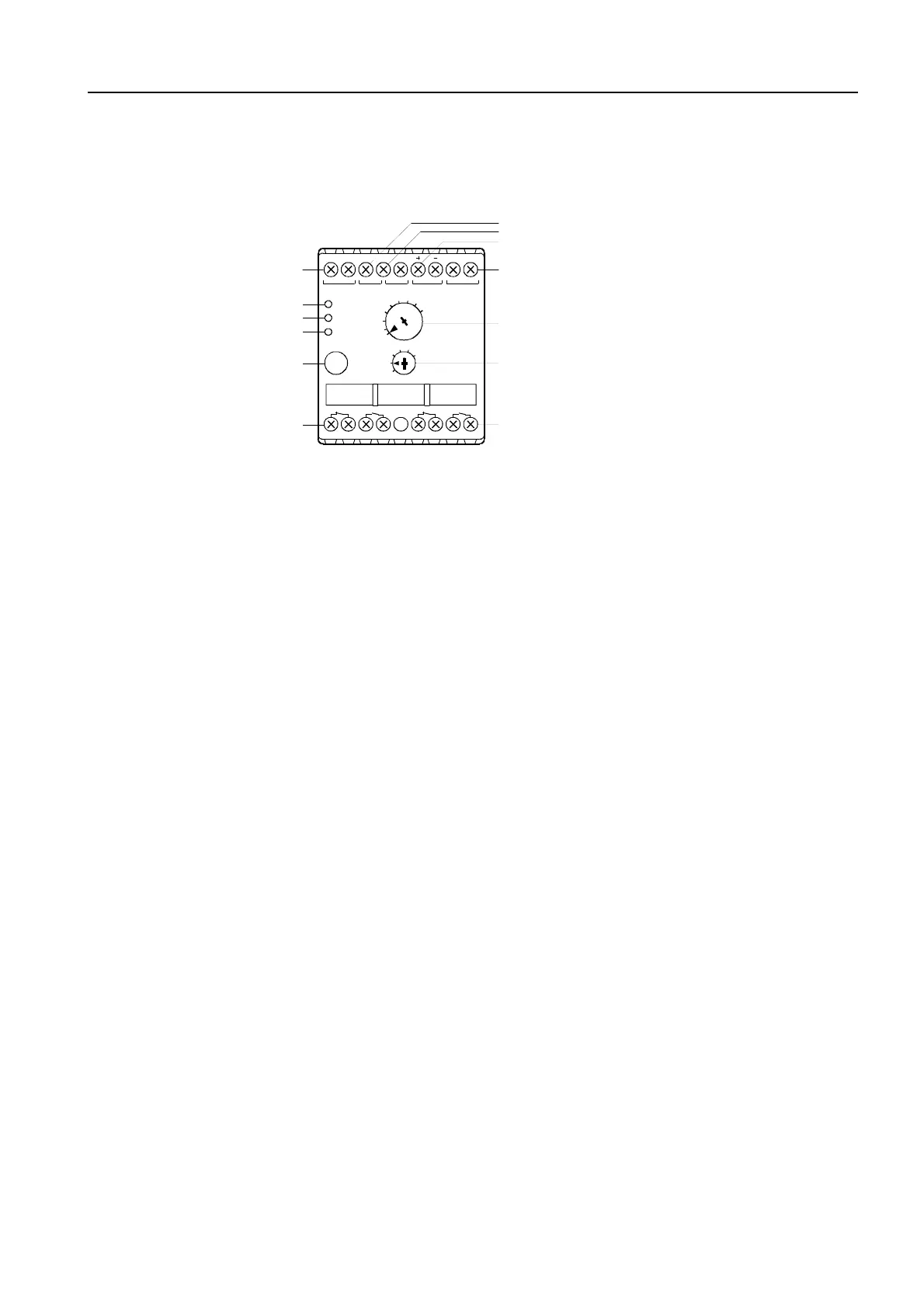
3RB12 front view:
Figure 4-10: Front view of the 3RB12 electronic overload relays
Functions
1 Terminals of the control supply voltage
2 Green "Ready" LED
3 Red "Ground Fault" LED
4 Red "Overload" LED
5 Combined test/reset button with function test
6 1 NO contact/1 NC contact for overload/thermistor tripping or
1 NO contact/1 NC contact for overload/thermistor or ground fault
tripping
7 Terminals for thermistor
8 Terminals for external summation current transformer
9 Terminals for remote or automatic reset
10 Rotary switch for current setting
11 Rotary switch for the class
12 1 NO contact/1 NC contact for ground fault tripping or 1 NO
contact/1 NC contact for overload warning
Overload
In the event of an overload > 110 % of the current
I
e
set using the rotary
switch on the front of the device, of current imbalance of 40 %
I
e
, or of
phase loss, tripping occurs through the switchover of two auxiliary contact
elements (1 NO contact: 97/98 / 1 NC contact: 95/96) after the tripping time
set by means of the six-step rotary switch (CLASS 5/10/15/20/25/30).
After overload tripping, the overload relay can be reset either by pressing
the test/reset button on the device or by remote or automatic reset after the
recovery time of 5 minutes elapses.
Thermistor detector
A tripping operation as a result of the thermistor detector responding takes
place via the same auxiliary contact elements as for overload tripping (1 NO
contact: 97/98 / 1 NC contact: 95/96), except that it is instantaneous.
The overload relay cannot be reset until the temperature in the motor wind-
ing 5 K has sunk to under the operating temperature of the thermistor.
95 96 97 98 05 06 07 08
NCNC
5
10
15
20 25
30
CLASS
25
30
40
50
60
70
80
90
100
A
Ready
Gnd Fault
Overload
TEST/
RESET
SIEMENS
A1 A2 T1 T2/C1 C2 Y1 Y2
3RB12
NSB00297
2
3
4
5
6
7
8
9
10
11
12
1
13

 Loading...


