3RV1 circuit breakers
SIRIUS System Manual
2-20
GWA 4NEB 430 0999-02b
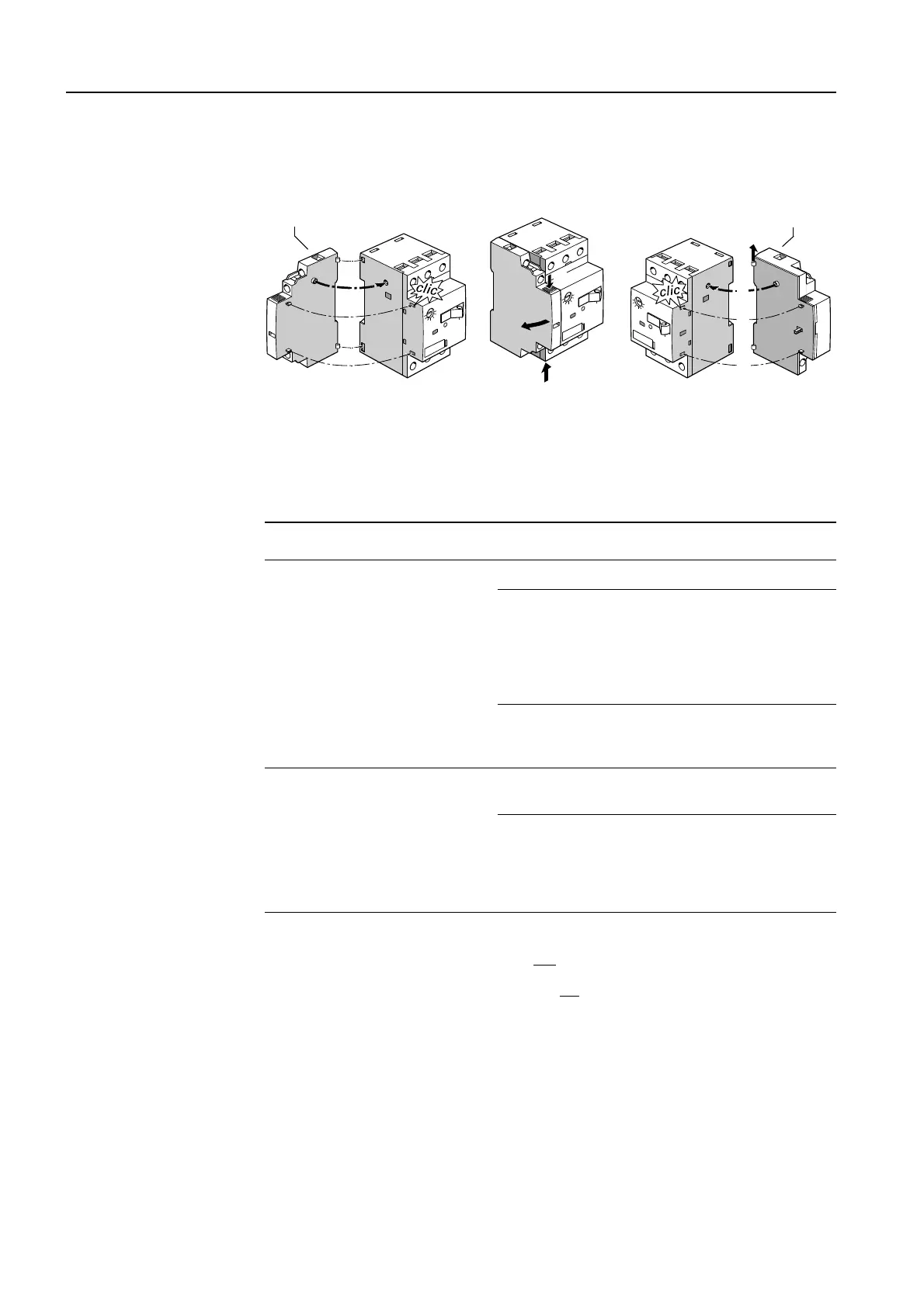
Lateral auxiliary switch (3RV1901-....)
Undervoltage release (3RV1901-....)
Figure 2-11: Mounting/removing the lateral auxiliary switch/undervoltage release (frame size S00)
Voltage ranges of the
auxiliary releases
One undervoltage release or shunt release can be installed for each circuit
breaker. The following voltage ranges are possible:
1
2
1
2
3
3
3
1
1
3RV 1901-.... 3RV 19.2-....
Auxiliary release Frequency
Undervoltage release
AC 50 Hz AC 60 Hz
24 V
110 V
230 V
400 V
415 V
120 V
208 V
240 V
480 V
Undervoltage release
with leading
auxiliary contacts
230 V
400 V
415 V
240 V
480 V
Shunt release
AC 50/60 Hz
100% duty cycle
1)
1) Transformer operational voltage of the lower mark of the voltage range at 0.85 (Tu = 60 °C)
is valid for 100% (continuous) duty cycle only
at AC 50/60 Hz
AC 50/60 Hz; DC
5 sec. duty cycle
2)
2) Transformer operational voltage of the lower mark of the voltage range at 0.9 (Tu = 60 °C) is
valid for 5 seconds duty cycle at AC 50/60 Hz and
DC
20 V - 24 V
90 V - 110 V
210 V - 240 V
350 V - 415 V
500 V
20 V - 70 V
70 V - 190 V
190 V - 330 V
330 V - 500 V
-
Table 2-6: Voltage ranges of the auxiliary releases

 Loading...


