EasyManuals Logo

Siemens SIRIUS System Manual

Siemens SIRIUS
425 pages
To Next Page IconTo Next Page
To Previous Page IconTo Previous Page
Page #193 background imageLoading...
Page #193 background image
3RT1/3RH1 contactors
SIRIUS System Manual
GWA 4NEB 430 0999-02b
3-85
Installation
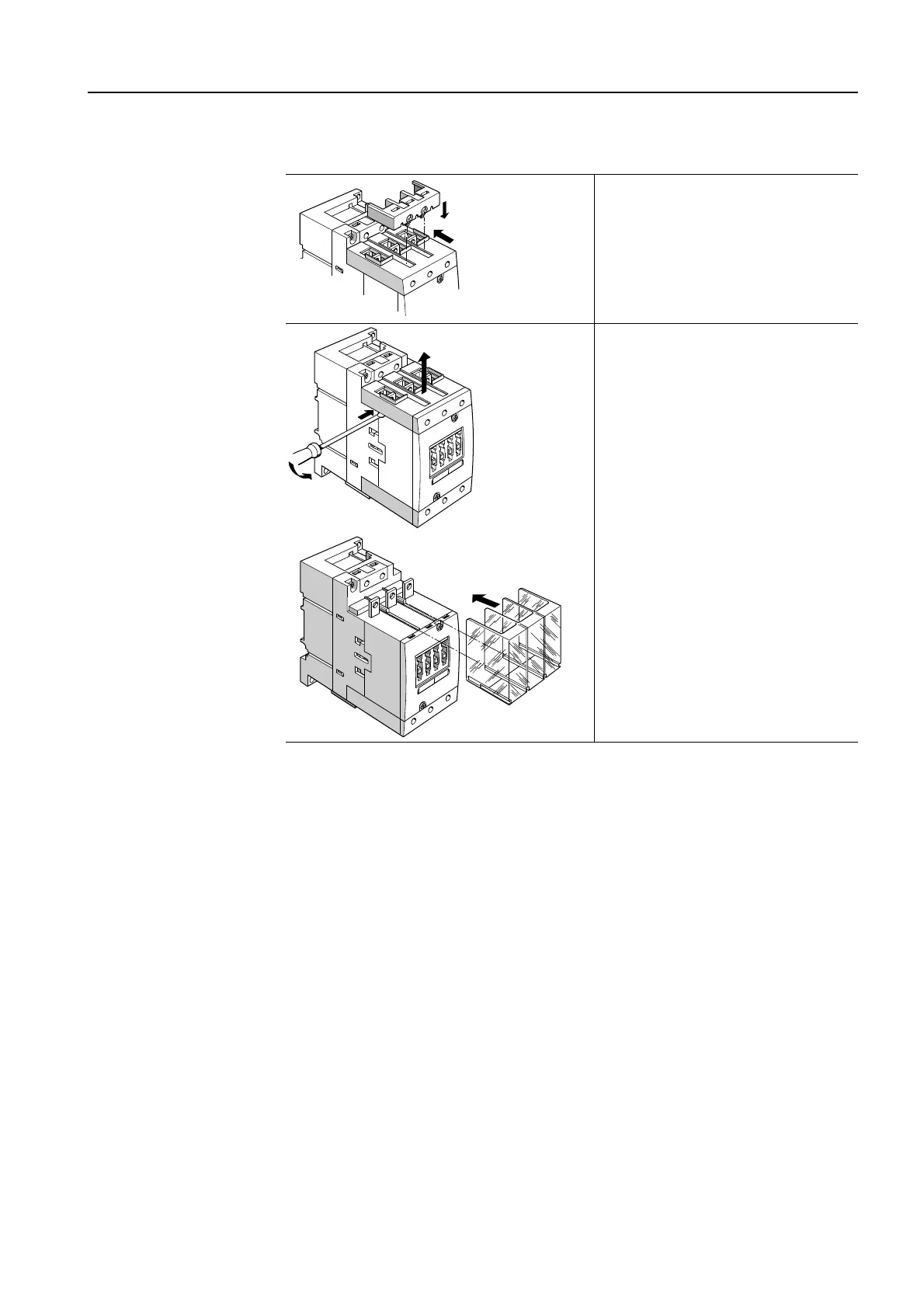
The following diagrams show you how to mount the covers:
Figure 3-66: Terminal covers
The cover for box terminals is
inserted in the guides on the box
terminal block and pushed back-
wards until it snaps into position.
To attach the cover for the lug
and bar connection, first remove
the box terminal block
(1, 2, 3)
,
and then push the cover in the
guide rails.
1
2
2
1
3
4

Table of Contents

Other manuals for Siemens SIRIUS

Questions and Answers:

Question and Answer IconNeed help?

Do you have a question about the Siemens SIRIUS and is the answer not in the manual?

Siemens SIRIUS Specifications

General IconGeneral
Product brand nameSiemens
SeriesSIRIUS
Coil Voltage24V DC, 110V AC, 230V AC
Switching CapacityUp to 10A
Mounting TypeDIN rail
Product designationSIRIUS
Contact MaterialSilver alloy
Contact RatingVaries depending on the specific SIRIUS relay model (e.g., 6 A at 250 V AC, 10 A at 250 V AC)
Switching VoltageVaries depending on the specific SIRIUS relay model (e.g., 250 V AC, 400 V AC)
Mechanical LifeUp to 10 million operations
Electrical LifeUp to 100, 000 operations
Operating Temperature-25°C to +55°C
Protection ClassIP20
Size of relay baseVaries depending on the specific SIRIUS relay model

Related product manuals