3RT1/3RH1 contactors
SIRIUS System Manual
GWA 4NEB 430 0999-02b
3-101
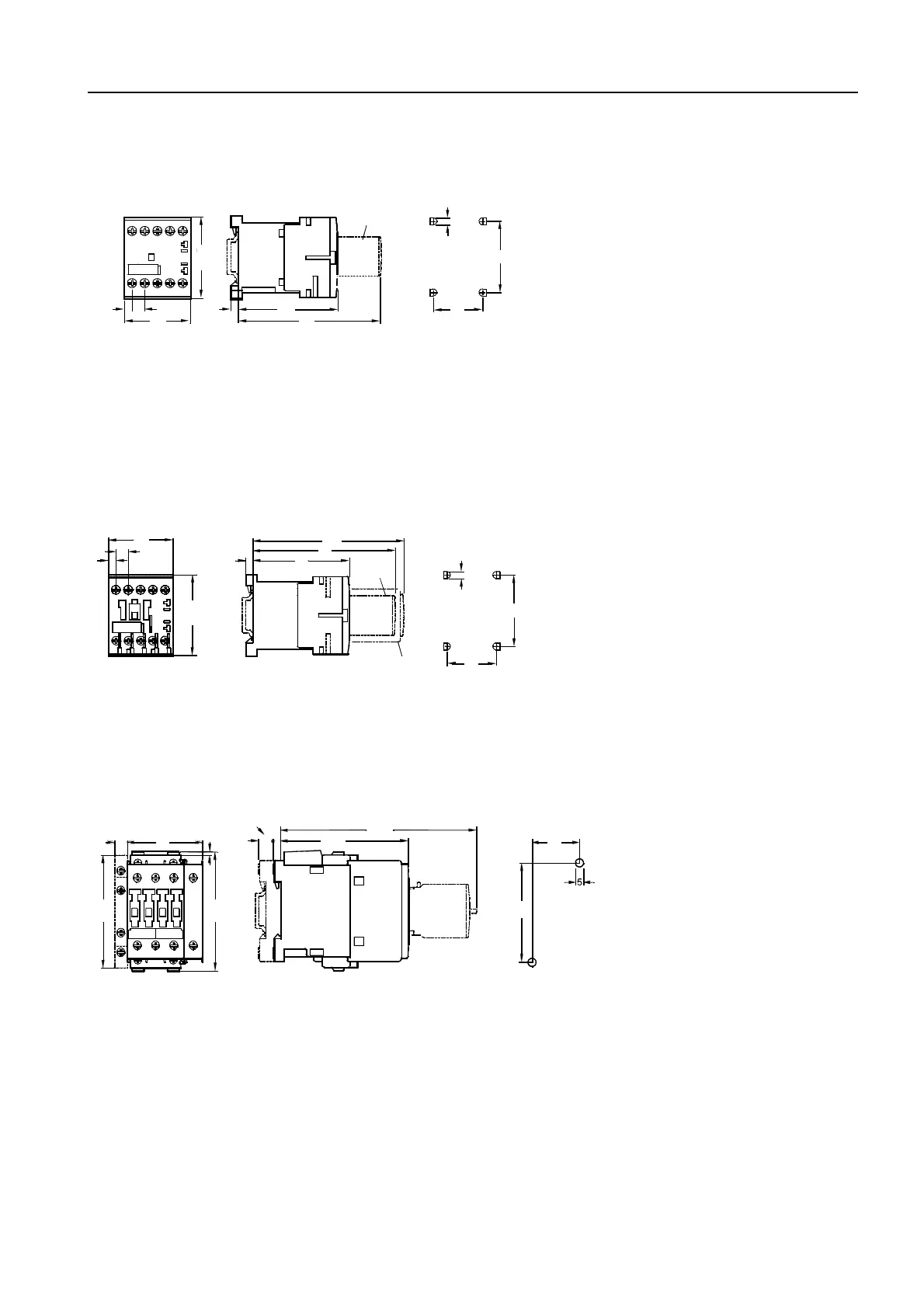
3RT10 contactor relays
Figure 3-84: 3RT10 1 (frame size S00)
with surge supressor
Different dimensions for contactor relays with Cage Clamp terminal: height 60 mm
3) Surge supressor
4) Drilling pattern
3RT10 2. contactor relay, see Figure 3-80
3RT13 and 3RT15 contactors, 4-pole
Figure 3-85: 3RT13 1, 3RT15 1 (frame size S00)
Screw-type terminal with surge suppressor, auxiliary switch block
Different dimensions for contactors with Cage Clamp terminals: height 60 mm, mounting depth with auxiliary switch block 110 mm
2) Auxiliary switch block (also electronically optimized variant 3RH19 11-1N...)
3) Surge supressor (also additional load module 3RT19 16-1GA00)
4) Drilling pattern
Distance to grounded parts at the side 6 mm
Figure 3-86: 3RT13 2, 3RT15 2 (frame size S0)
with surge supressor and auxiliary switch block
a = 3 mm at < 250 V and attachment of surge suppressor
a = 7 mm at > 250 V and attachment of surge supressor
b = DC 10 mm deeper than AC
1) Auxiliary switch block, attachable at the side (left)
2) Auxiliary switch block, attachable at the front, (max. two 1-pole auxiliary switch blocks)
3) Surge supressor
4) Drilling pattern
NSB00258a
57,5
8,6
5,3
45
67
99
5
35
50
5
3
4
NSB00757a
57,5
5,3
8,6
5
67
99
106
1
2
35
50
5
3
45
NSB 00758e
b
10 61
86
5
10
135
35
2
4

 Loading...


