3RA1 fuseless load feeders
SIRIUS System Manual
5-28
GWA 4NEB 430 0999-02b
5.7 Technical specifications
Installation regulations for 400/500 VAC
Installation regulations for 690 VAC
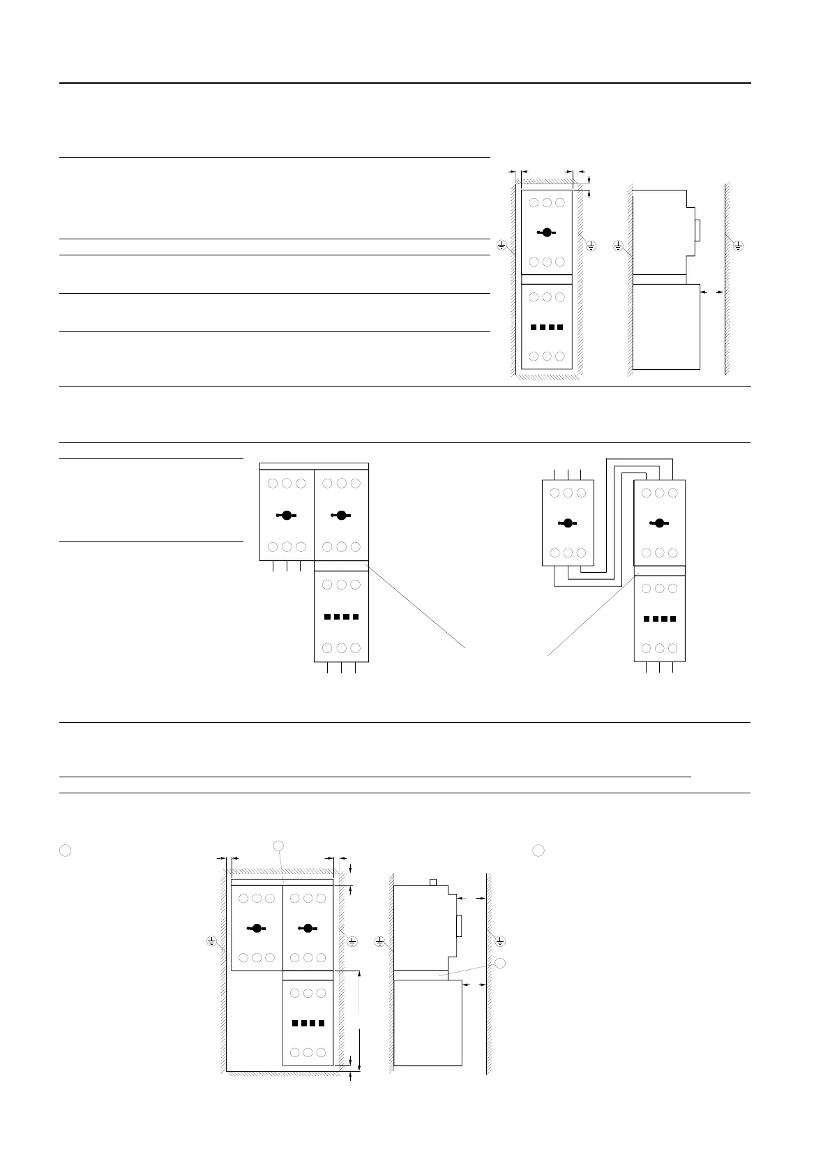
When installing the combinations, the following clearances must be maintained to grounded parts:
Circuit breakers
combined with contactors
Clearances to grounded or
live parts
Circuit
breaker
Contactor Rated operational
voltage
Y
mm
X2
1
)
mm
Z
mm
3RV1. 1 with 3RT10 1 400/500 V 20 10 9
3RV1. 2 with 3RT10 1
3RT1.2
3RT1.3
400/500 V
400/500 V
400/500 V
30
30
30
10
10
10
9
9
9
3RV1. 3 with 3RT10 2
3RT1.3
3RT10 4
400/500 V
400/500 V
400/500 V
50
50
50
10
10
10
10
10
10
3RV1. 4 with 3RT10 4
3RT10 4
400 V
500 V
90
220
10
10
12
20
1) Minimum clearance to the contactor at the front. A minimum clearance at the front is not required for a circuit breaker.
Frame size Format
Standard format for frame sizes S0 to 5.5 kW, S2, and S3
Format for frame size S0 from 7.5 to 11 kW
S0
Mounted on an insulated
base plate. In screw-on
mounting, the screws
must not be grounded.
Alternatively, the rail adap-
ter can be used without
restrictions.
S2/S3
Mounted on an insulated
base plate. Alternatively,
the rail adapter can also be
used.
When installing the combination, the following clearances must be maintained to grounded
parts:
2 circuit breakers combined with contactors Clearance to grounded or live parts
Circuit
breaker
Contactor Rated operational
voltage
Y1
mm
Y2
mm
Y3
mm
X1
mm
X2
mm
X3
mm
3RV1. 2 with 3RT10 1 690 V 80 10 95 20 14 20
3RV1. 3 with 3RT10 3 690 V 50 10 120 10 32 10
3RT10 4 690 V 50 10 120 10 40 10
3RV1...
3RT1...
1L1 3L2 5L3
2T1 4T2 6T3
1L1 3L2 5L3
2T1 4T2 6T3
NSB01030b
3RV1...
3RT1...
Z
Y
Z
X2
NSB01032b
3RV1...
3RV1...
3RT1...
1L1 3L2 5L3 1L1 3L2 5L3
2T1 4T2 6T32T1 4T2 6T3
1L1 3L2 5L3
2T1 4T2 6T3
Load side
Infeed side
NSB01031c
3RV1...
3RV1...
3RT1...
1L1 3L2 5L3 1L1 3L2 5L3
2T1 4T2 6T32T1 4T2 6T3
1L1 3L2 5L3
2T1 4T2 6T3
Load side
Infeed side
3-phase busbar
Frame size S0:
3RV19 15-1A
Frame size S2:
3RV19 35-1A
Link module
see accessories
S0: 3RV19 15-1A
S2: 3RV19 35-1A
3-phase busbar
1
In a combination
involving a circuit breaker
of frame size S2 and a
contactor of frame size
S3, a clearance of 10 cm
must be maintained
2
3RV1...
3RV1...
3RT1...
1L1 3L2 5L3 1L1 3L2 5L3
2T1 4T2 6T32T1 4T2 6T3
1L1 3L2 5L3
2T1 4T2 6T3
NSB01033 c
3RV1...
3RT1...
Z
Y1
Z
Y2
Y3
X2
X1
1
2

 Loading...


