3RT1/3RH1 contactors
SIRIUS System Manual
3-90
GWA 4NEB 430 0999-02b
Two-conductor connec-
tion
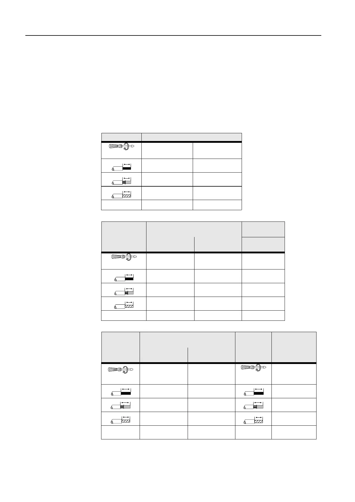
It is possible with all the main, auxiliary, and control cable connections to
connect two conductor ends. They can also be used to connect untreated
conductors with different cross-sections. Box terminals each with 2 terminal
points are provided for the main conductor connection in contactors of
frame sizes S2 and S3.
This connection method also promises problem-free looping and parallel
connection without intermediate terminals.
Conductor cross-sec-
tions
Permissible conductor cross-sections for main and auxiliary connections:
S00
S0
S2
Main and auxiliary conductors
∅
5 to 6 mm / PZ2
0.8 to 1.2 Nm
7 to 10.3 lb.in
Cage Clamp
2 x (0.5 to 1.5 mm²)
2 x (0.75 to 2.5 mm²)
2 x (0.25 to 2.5 mm²)
2 x (0.5 to 1.5 mm²)
2 x (0.75 to 2.5 mm²)
2 x (0.25 to 1.5 mm²)
---- 2 x (0.25 to 2.5 mm²)
AWG
2 x (18 to 14) 2 x (24 to 14)
Control conductor: A1/A2
Auxiliary conductor: NO/NC
Main conductor
Screw-type termi-
nal
Cage Clamp termi-
nal
L1 L2 L3
T1 T2 T3
∅
5 to 6 mm / PZ2
0.8 to 1.2 Nm
7 to 10.3 lb.in
----
2 to 2.5 Nm
18 to 22 lb.in
2 x (0.5 to 1.5 mm²)
2 x (0.75 to 2.5 mm²)
2 x (0.25 to 2.5 mm²)
2 x (1 to 2.5 mm²)
2 x (2.5 to 6 mm²)
2 x (0.5 to 1.5 mm²)
2 x (0.75 to 2.5 mm²)
2 x (0.25 to 1.5 mm²)
2 x (1 to 2.5 mm²)
2 x (2.5 to 6 mm²)
---- 2 x (0.25 to 2.5 mm²) ----
AWG
2 x (18 to 14) 2 x (24 to 14) 2 x (14 to 10)
Control conductor: A1/A2
Auxiliary conductor: NO/NC
Main conductor
Screw-type termi-
nal
Cage Clamp termi-
nal
L1 L2 L3
T1 T2 T3
∅
5 to 6 mm / PZ2
0.8 to 1.2 Nm
7 to 10.3 lb.in
----
∅ 5 to 6 mm /
PZ2
3 to 4.5 Nm
27 to 40 lb.in
2 x (0.5 to 1.5 mm²)
2 x (0.75 to 2.5 mm²)
2 x (0.25 to 2.5 mm²) 2 x (0.75 to 16 mm²)
2 x (0.5 to 1.5 mm²)
2 x (0.75 to 2.5 mm²)
2 x (0.25 to 1.5 mm²)
2 x (0.75 to 16 mm²)
1 x (0.75 to 25 mm²)
---- 2 x (0.25 to 2.5 mm²)
2 x (0.75 to 25 mm²)
1 x (0.75 to 35 mm²)
AWG
2 x (18 to 14) 2 x (24 to 14)
AWG
2 x (18 to 3)
1 x (18 to 2)
10
10
10
10
10
10
10 13
10
10

 Loading...


