3RA1 fuseless load feeders
SIRIUS System Manual
5-30
GWA 4NEB 430 0999-02b
Conductor cross-sections - main circuit
1) After the box terminals have been removed, lug or busbar connections are possible.
Specifications IEC 60 947-1, EN 60 947-1 (VDE 0660 Part 100)
IEC 60 947-2, EN 60 947-2 (VDE 0660 Part 101)
IEC 60 947-4-1, EN 60 947-4-1 (VDE 0660 Part 102)
Ty p e
Frame size
Number of poles
3RA1.1
S00
3
3RA1. 2
S0
3
3RA1. 3
S2
3
3RA11 4
S3
3
Connection type
Terminal screw
Screw-type
terminal
Pozidriv 2
Screw-type
terminal
Pozidriv 2
Box terminal
Pozidriv 2
Box terminal
Allen screw
Minimum/maximum conductor cross-sections
Finely stranded with wire end ferrule
- 1-wire
- 2-wire
Single- or multi-core
- 1-wire
- 2-wire
Ribbon conductor
Bar connection
Single- or multi-core
Multi-core
mm
2
mm
2
mm
2
mm
2
AWG
AWG
0.5/2.5
0.5/2.5
0.5/4
0.75/2.5 (max. 4)
–
–
2 x (18 to 14)
–
1/6
1/2.5 to 2.5/6
1/6 (max. 10)
1/2.5 to 2.5/6
–
–
2 x (14 to 10)
–
0.75/25
0.75/16
0.75/35
0.75/25
yes
–
2 x (30 to 2)
–
2.5/50
1
)
2.5/35
1
)
2.5/70
1
)
2.5/50
1
)
yes
yes
–
2 x (10 to 1/0)
Connection type
Cage Clamp terminal
mm
2
AWG
2 x (0.5 to 2.5)
2 x (18 to 14)
–
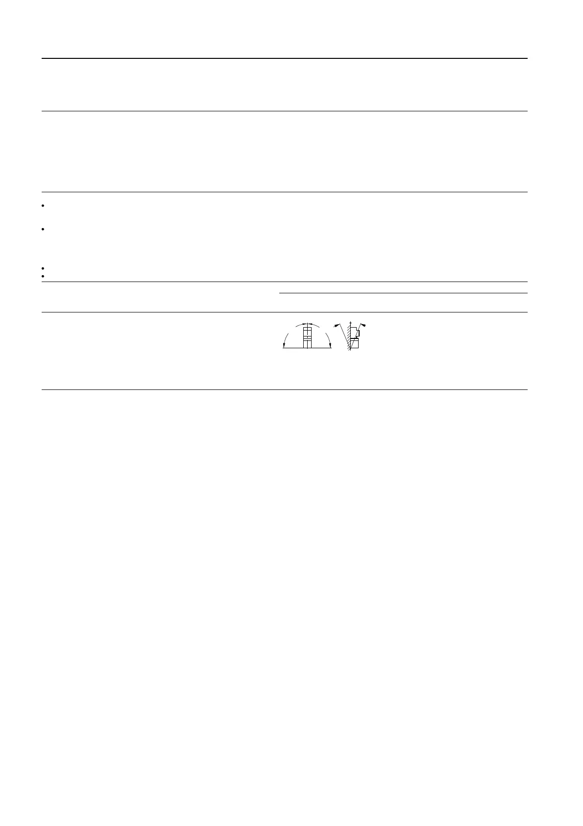
Permissible installation position
Important:
In acc. with DIN 43 602
Start command "
I
"
right or above
90°
90°
NSK-7666
22,5°
22,5

 Loading...


