TXP-CLC Course
4
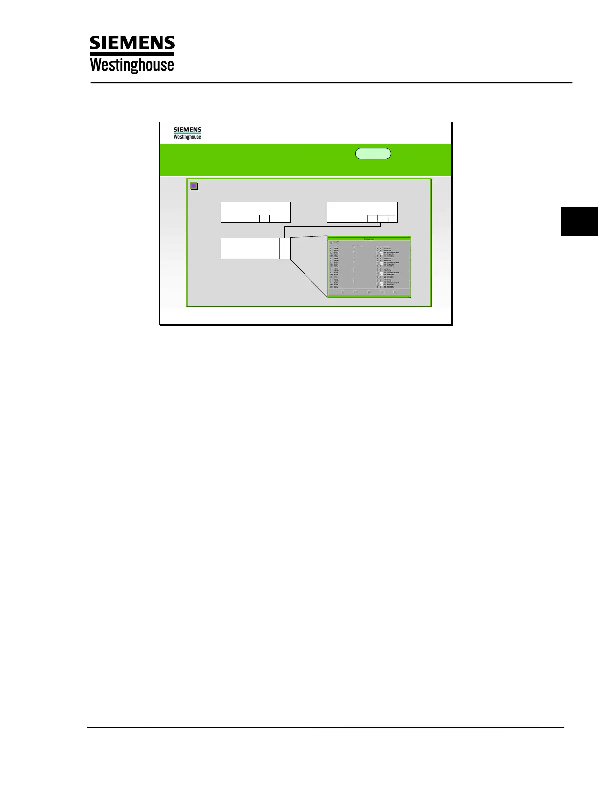
Design of the arrangement diagrams in ES 680
The AS structure diagram (YDM)
I
I
M
M
SIM
SIM
AP A
AP A
AP B
AP B
Graphical design of the cabinet allocation with
Graphical design of the cabinet allocation with
subracks
subracks
The hardware of the automation system is displayed in this diagram in detail
beginning with the central unit and the sub-racks that are connected to it (FUM,
expansion rack, SIM stations, etc.) The type of sub-rack and its mounting
location in the cabinet are also specified here.
Training Center
Copying of this document, and giving it to others and use or communication of the contents, are forbidden without express authority. Offenders are liable to the payment of
damages. All rights are reserved in the event of the grant of a patent or the registration of a utility model or design.
7