TXP-CLC Course
channel identification code signal
2 MAJ15 CP012
2 MAJ15 CP012
2 MAJ 15 C L007
XQ01
XQ02
XQ01
1
2
4
3
5
6
8
7
9
10
12
11
13
15
14
16
location equipm. describtion
unit/cabinet
rack/plug in place
key
product No.
component
OK return close
2 CRF01
info
.AG019
S
I
M
4
3
1
S
I
M
4
5
1
S
I
M
4
6
4
S
I
M
4
6
4
S
I
M
4
3
1
S
I
M
4
7
0
S
I
M
4
7
0
S
I
M
4
3
1
S
I
M
4
5
1
S
I
M
4
3
1
S
I
M
4
8
2
S
I
M
4
8
2
KA GB GA TT KB AS AS AS AS BAZ RA XB
003 011 018 027 035 043 0 51 054 067 075 083 091 099 107 115 123 131 139 147 155 163
SIM ET200
module parameter
SIM431GA
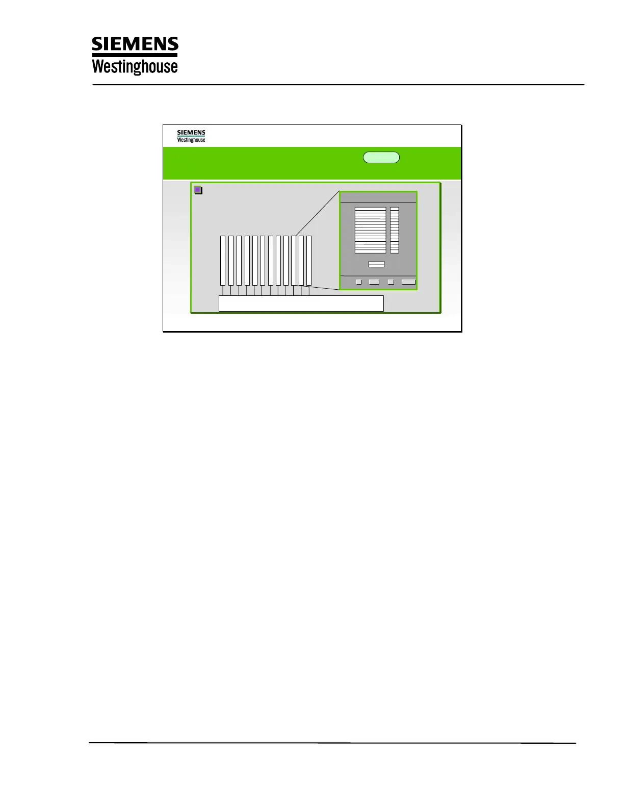
Graphical design of the
Graphical design of the
subrack
subrack
allocation with modules
allocation with modules
Design of the arrangement diagrams in ES 680
The AS module structure diagram (YDR)
The module occupancy is displayed for the sub-racks (FUM, SIM) in this diagram
and slots are allocated. Checks ensure that certain modules are only inserted
into specific slots in the sub-rack.
The channels are assigned in the parameter windows for the modules. This is the
correlation between the topology diagram and the function diagram of the
individual level.
Training Center
Copying of this document, and giving it to others and use or communication of the contents, are forbidden without express authority. Offenders are liable to the payment of
damages. All rights are reserved in the event of the grant of a patent or the registration of a utility model or design.
8