TXP-CLC Course
4
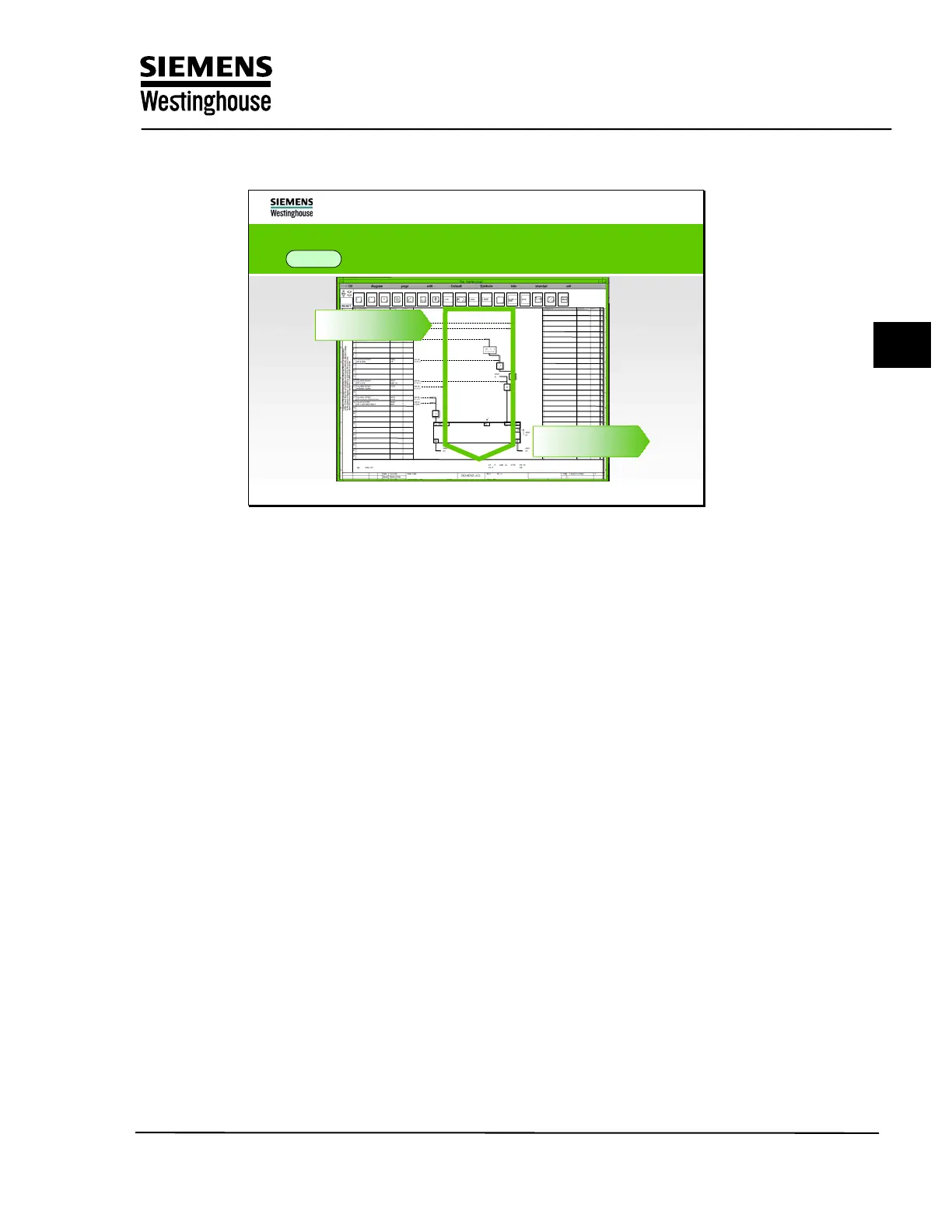
I&C solutions are designed in
ES 680 with the logic diagram (YFR)
DCM
Signal flow
Signal flow
Outputs
Outputs
Inputs
Inputs
The function diagrams for the single-loop level must always be created and the
code is generated for the program to be executed in the target system from these
diagrams.
Each single-loop level function diagram contains an input side, a logic area, and
an output side. Signals are brought in from the input side, logic performed on
them, and output on the output side.
Training Center
Copying of this document, and giving it to others and use or communication of the contents, are forbidden without express authority. Offenders are liable to the payment of
damages. All rights are reserved in the event of the grant of a patent or the registration of a utility model or design.
9