TXP-CLC Course
4
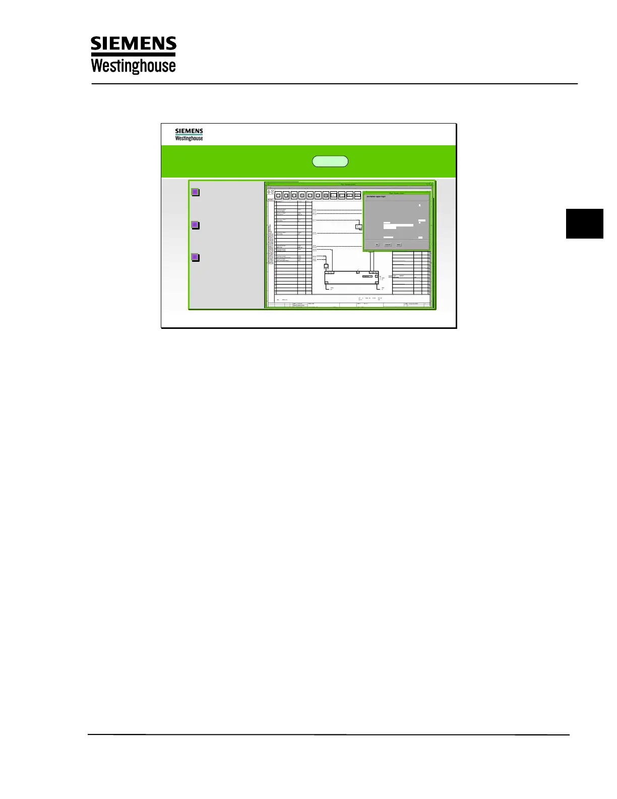
The AS 620 logic diagram in ES 680
Parameterization
via parameter
masks
Graphical design
of the signal flow
Automatic
code generation
Default
Symbols
info
standart exit
DB diagram
page
edit
DCM
motor/solenoid valve
channel 1
>1
SIEMENS AG
ID-code
signal
Xdescription
Xsetting
XADRESS 1
SEND_ADR1
XAG
XPB/OB
XFGC
Dest. ID-code
SAH
Ydescription
Ysetting
YADDRESS 1
REC_ADR 1
YAG
YPB/OB
YFGC
XUNIT
XADDRESS 2
SEND_ADR2
XKP
XPB
YADDRESS 2
REC_ADR 2
YKP
YPB
DFK
XSP
0
69
DEST
YSP
0
0
INDEX
7 0LAC10 AP001
XA92
EFP A MTR
OM
6
102
FG11
7 0LAB30 CP001
0
0
Screen forms are available for parameterizing the function blocks. Internal
parameters such as delay time and controller parameters can be set in these
screen forms. Many basic definitions are preset with defaults, so that changes
only have to be made in these windows for special applications.
All changes to the task definition are also entered via the function diagram and
converted by the engineering system into the system- specific code. This method
of consistent forward documentation ensures that the data is always consistent in
the AS and OM.
Training Center
Copying of this document, and giving it to others and use or communication of the contents, are forbidden without express authority. Offenders are liable to the payment of
damages. All rights are reserved in the event of the grant of a patent or the registration of a utility model or design.
11