page 10 579-1150 Rev M
4010ES IDNAC Fire Alarm System Installation Guide
3 Basic hardware
The 4010ES FACUs are one-bay or two-bay back boxes with a dead front and glass door, containing a set of pre-installed basic system
components:
• Dead front-mounted CPU (2 x 40 character LCD or InfoAlarm)
• Operator interface
• Extended system supply (ESS) providing IDNAC addressable appliance control and system power with IDNet2
• 48-LED Module (for some 4010ES configurations)
• IDNet2 (2 Bay systems)
• PDI Blocks for optional modules
In addition to the basic modules, optional modules can be installed inside the one-bay or two-bay 4010ES panels. The types of modules
available depend on the panel configuration as well as the accessibility and availability of the power distribution interface (PDI) blocks. The
number of available PDI blocks depends on the system ordered. See Panel configurations.
3.1 CPU
The CPU card (Figure 7 and Figure 8) is the main decision maker in the 4010ES FACU. It holds all job information, current system status and
communicates to all slaves connected to the 4010ES panel. A 4010ES CPU contains the following features:
• 2 x 40 LCD display and piezo (non-InfoAlarm systems only) - Annunciation for supervisory, trouble, priority 2 and fire alarm
signals.
• Compact Flash Socket (card pre-installed) - Alternate Exec and Job storage.
• Ethernet Service port - PC connection used by Simplex service personnel.
• Serial Service port - Interface for service equipment or Simplex service personnel.
• Class A/B Remote Unit Interface - Remote connection to system components not located within 4010ES box.
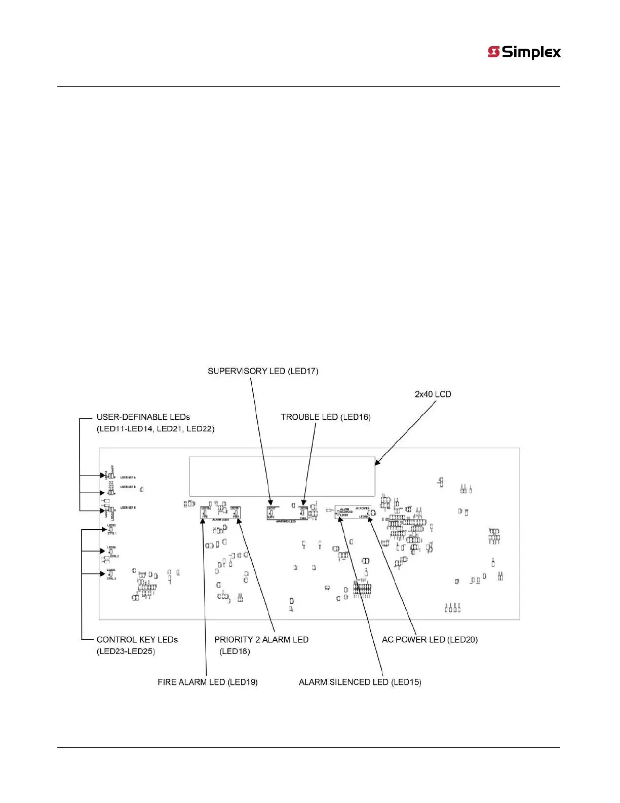
Figure 7: Dead front mounted CPU with a 2 x 40 display (front view)
Note: All LEDs on the front side of the board are used for standard fire alarm functions and are visible through the dead front membrane.