page 52 579-1150 Rev M
4010ES IDNAC Fire Alarm System Installation Guide
7 ESS field wiring
This chapter describes the wiring between the ESS card and compatible devices.
General wiring guidelines
• Conductors must test free of all grounds. See Checking system wiring.
• All wiring must be done using copper conductors only, unless noted otherwise.
• If shielded wire is used:
- The metallic continuity of the shield must be maintained throughout the entire cable length.
- The entire length of the cable must have a resistance greater than 1 megohm to earth ground.
• Underground wiring must be free of all water.
• In areas of high lightning activity, or in areas that have large power surges, the 2081-9027 Transient Suppressor should be used on
monitor points.
• Wires must not be run through elevator shafts.
• Splicing is permitted. All spliced connections must either be soldered (resin-core solder), crimped in metal sleeves, or encapsulated
with an epoxy resin. When soldering or crimped metal sleeves are used, the junction must be insulated with a high-grade electrical
tape that is as sound as the original insulating jacket. Shield continuity must be maintained throughout.
• A system ground must be provided for earth detection and lightning protection devices. This connection must comply with approved
earth detection per NFPA780.
• Only system wiring can be run together in the same conduit.
7.1 ESS IDNet wiring
A single IDNet2 channel is provided that can connect up to 250 IDNet devices. The IDNet2 channel has two isolated circuits that support
either Class A or Class B wiring. Class X wiring can be supported through the use of IDNet isolator devices. Typical devices include smoke
and heat sensors, QuickConnect sensors and a variety of addressable input and/or output modules. Refer to datasheet S4090-0011 for a
list of compatible IDNet devices.
Class A wiring provides an alternate communication path that provides communications to all devices when a single open circuit fault
occurs. Class A wiring requires two wires to be routed from the IDNet Primary Terminals (B+, B-) to each IDNet device, and then back to the
IDNet Secondary Terminals (A+, A-).
Note: Wiring is in/out. “T” tapping is not allowed.
Class B wiring allows “T” tapping, and typically results in less wiring used per installation compared to Class A. IDNet wiring is inherently
supervised due to individual device level communications, and end-of-line resistors are not required.
Class X wiring improves on Class A wiring by providing resilience not only to single open fault but also to single short-circuit fault. Class X
requires the use of IDNet isolator devices.
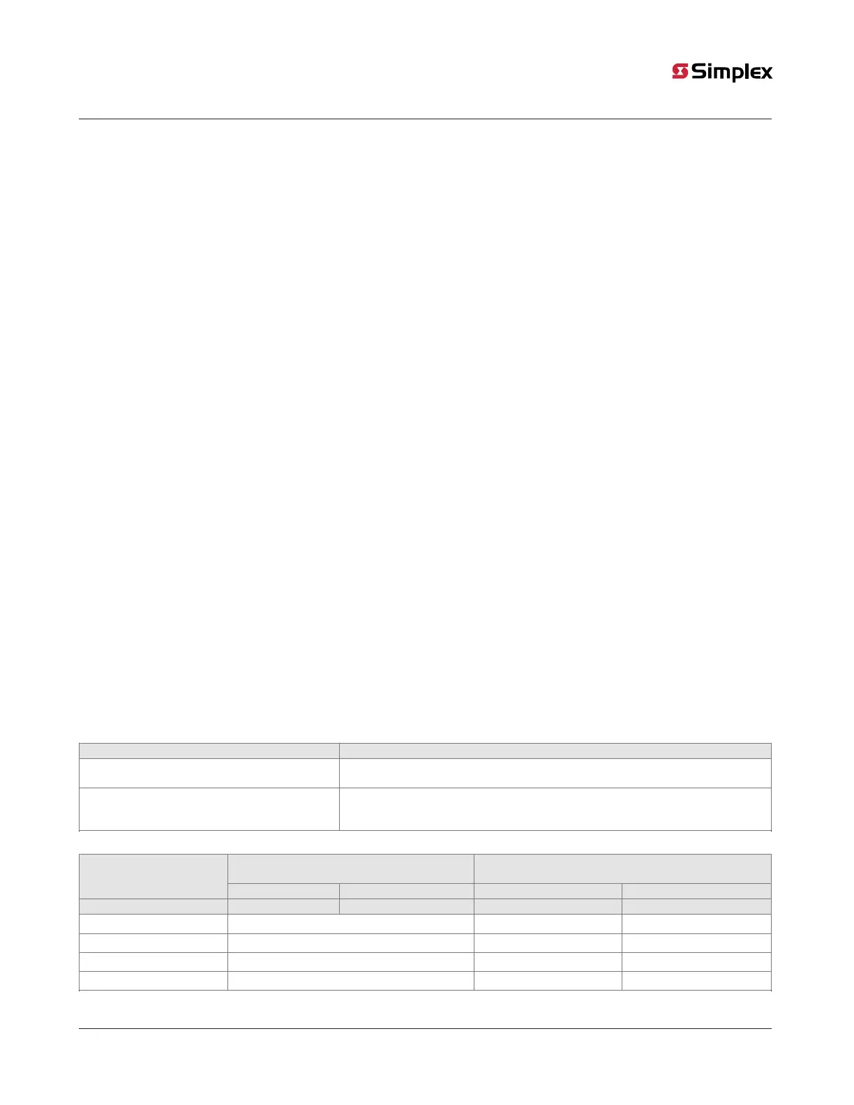
7.1.1 Wiring parameters
Table 30 identifies the ESS IDNet wiring parameters that must be considered when applying this module. For additional wiring information,
see the applicable installation documentation or contact your authorized Simplex Product supplier.
Table 29: ESS IDNet wiring capacitance parameters
Parameter Value
Maximum supported channel capacitance; Total of
both isolated outputs
The sum of line-to-line capacitance, plus the capacitance of either line-to-shield (if
shield is present) = 0.6µF (600nF)
Capacitance between IDNet SLCs wiring (between
wires of the same polarity; plus to plus, minus to
minus)
1µF maximum (this is for multiple IDNet channels)
Table 30: IDNet wiring distance limits
Class B wiring, total channel wiring
parameters, Including T-Taps
Class A/X wiring, total channel wiring parameters
Channel loading
Up to 125 devices 126 to 250 devices Up to 125 devices 126 to 250 devices
Total loop resistance 50Ω maximum 35Ω maximum 50Ω maximum 35Ω maximum
18AWG (0.82mm
2
)
12,500ft (3.8km) 4000ft (1219m) 2500ft (762m)
16AWG (1.31mm
2
)
12,500ft (3.8km) 5000ft (1524m) 2500ft (762m)
14AWG (2.08mm
2
)
12,500ft (3.8km) 5000ft (1524m) 2500 ft (762m)
12AWG (3.31mm
2
)
12,500ft (3.8km) 5000ft (1524m) 2500ft (762m)