page 53 579-1150 Rev M
4010ES IDNAC Fire Alarm System Installation Guide
Table 30: IDNet wiring distance limits
Class B wiring, total channel wiring
parameters, Including T-Taps
Class A/X wiring, total channel wiring parameters
Channel loading
Up to 125 devices 126 to 250 devices Up to 125 devices 126 to 250 devices
Total loop resistance 50Ω maximum 35Ω maximum 50Ω maximum 35Ω maximum
Note: Maximum wiring distance is determined by either reaching the maximum resistance, the maximum capacitance, or the stated max-
imum distance, whichever occurs first. Class A/X maximum distances are to the farthest device on the loop from either “B” or “A” termi-
nals. For Class B wiring, the maximum distance to the farthest device is limited to the stated Class A/X wiring distances. Shielded wire is
not required. Twisted wire is recommended for improved noise immunity.
Note: External wiring must be shielded (for lightning suppression) and 2081-9044
Overvoltage Protectors must be installed at building exit and entrance locations.
Capacitance; each protector adds 0.006µF across the connected line.
Resistance; each protector adds 3Ω per line of series resistance; both IDNet lines
are protected; 6Ω per protector will be added to total loop resistance.
Maximum distance of a single protected wiring run is 3270ft (1km).
IDNet wiring considerations using 2081-9044
Overvoltage Protectors
(2081-9044 is UL listed to Standard 60950-1,
Standard for Safety of Information Technology
Equipment)
Refer to document number 574-832, 2081-9044 Overvoltage Protector Installation
Instructions, for additional information.
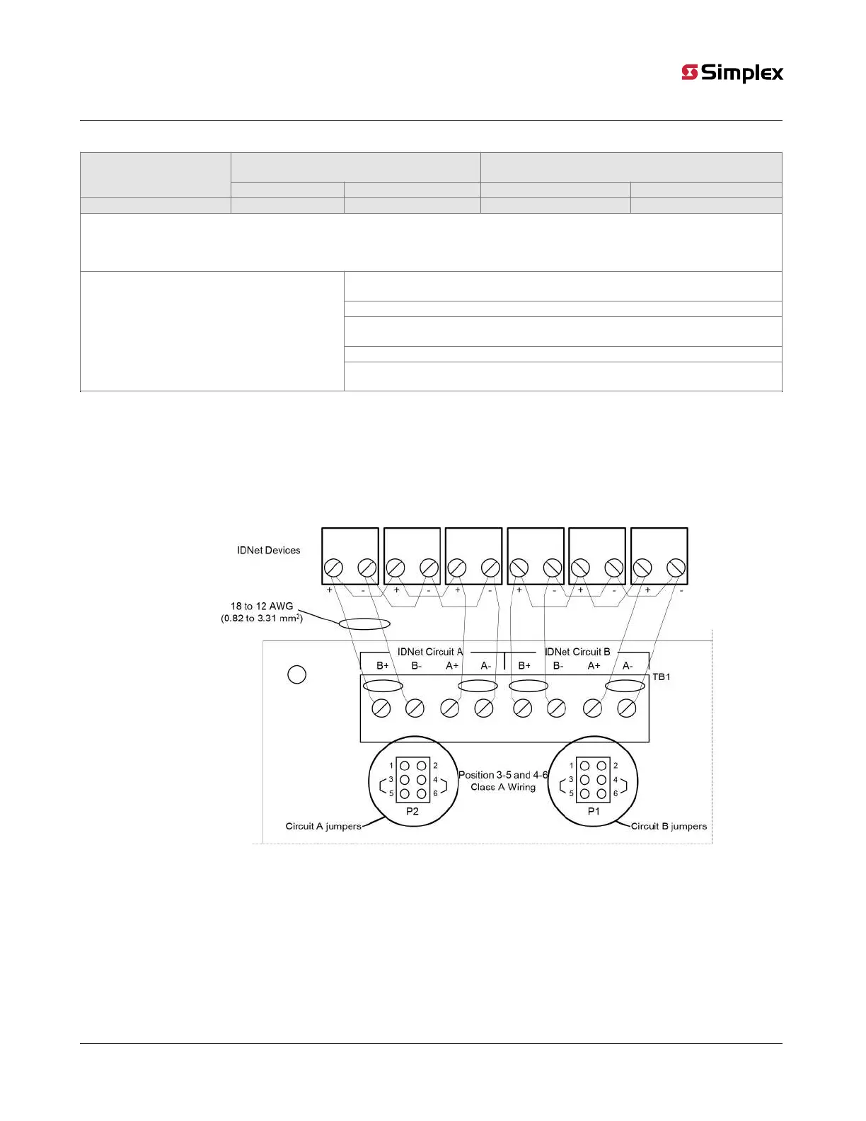
7.1.2 Class A wiring
To connect the ESS with an IDNet2 channel to devices using Class A wiring, read the following instructions and refer to Figure 41:
1. Route wiring from the IDNet Circuit Primary Terminals (B+, B-) on TB1 of the IDNet terminal to the appropriate inputs on the first
IDNet device.
2. Route wiring from the first IDNet device to the next as in/out as shown in Figure 41. Repeat for each device.
3. Route wiring from the last IDNet device to the IDNet Circuit Secondary Terminals (A+, A) on TB1 of the IDNet terminal.
4. Ensure that circuit jumpers are configured for Class A operation.
Figure 41: Class A wiring
Note: Set jumpers to Positions 3-5 and 4-6 to select Class A operation. (Refer to P1 and P2 in Figure 41 for correct orientation)
Note:
a. If no remote isolators or isolator bases are on the loops, device addressing can be assigned without concern for
sequence.
b. If remote isolators or isolator bases are on the loops, the required addressing approach is to start from the “B” side
of the A Loop output and assign each successive isolator a higher address than the isolator it proceeds. Follow this
sequencing through to the “B” side of the B Loop.
There are two considerations for addressing Class A wired IDNet devices connected to the IDNet terminal: