page 35 579-1150 Rev M
4010ES IDNAC Fire Alarm System Installation Guide
6 Installing 4010ES systems
This chapter describes how to mount the 4010ES back boxes to a wall, and install basic system components into the boxes.
Before beginning the installation, review this chapter to get a sense of the types of bays and modules that make up the FACU.
Important: Verify ES Panel Programmer, Executive, and Slave Software compatibility when installing or replacing system components.
Refer to the technical support website for up-to-date compatibility information.
6.1 Mounting the panel
6.1.1 Installing the back box
Store the system electronics containers in a safe, clean, and dry location until the back box installation is completed, and you are ready to
install additional modules. Make certain that you have the necessary hardware before you begin the installation procedure.
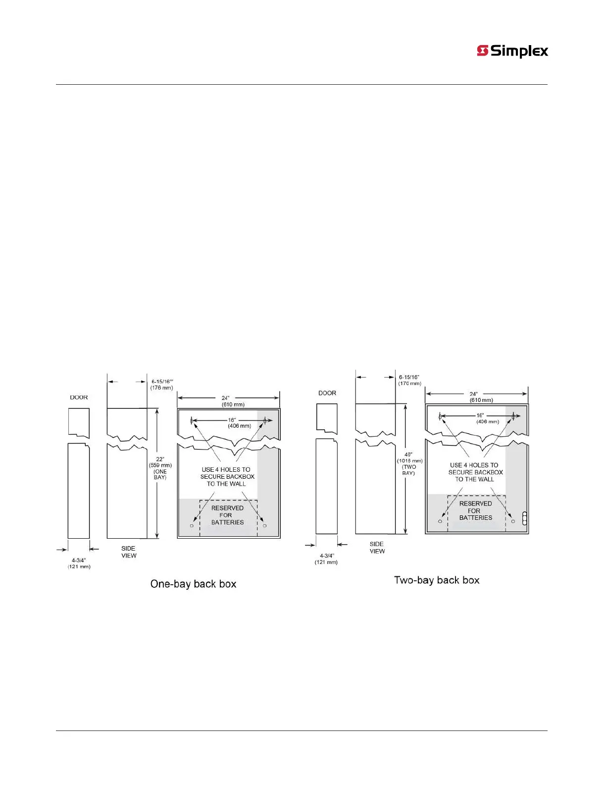
Install the back box as shown in Figure 21. Use the holes in the back box to secure it to the wall.
Note:
• Conductor entrance and routing restrictions apply to power-limited systems only.
• While the pre-installed system components may be left in the backbox during installation, due to the danger of metal fragments falling
into electronics, it is recommended to remove the dead front and any bay pans in the system.
• For surface or flush mounting to a wooden wall structure, the back box must be attached with four 1-½-inch-long (38 mm) lag bolts
and four ½-inch-diameter (13 mm) washers.
• For surface mounting, secure the box to the wall using the tear-drop mounting holes on the back surface. For flush and semi-flush
mounting, secure the box to the wall studs using the indicated areas (dents in the metal) on the sides of the box. Note that the front
surface of the back box must protrude at least three inches from the wall surface for semi-flush installations.
• Power-limited systems have entrance and routing restrictions for field wiring. See Figure 27 for more details.
Figure 21: Back box installation
Note:
1. Use suitable punch when conduit is required. Cut conduit entrance holes on-site to ensure proper location.
2. Minimum distance between boxes is 3 1/4 inches (83mm) to ensure proper door opening.