page 68 579-1150 Rev M
4010ES IDNAC Fire Alarm System Installation Guide
10 Appendix A: ULC programming requirements
This appendix discusses the programming operations that must be met to comply with Canadian Underwriter’s Laboratory (ULC)
standards.
10.1 Common earth fault ground indicator
This application monitors a system pseudo (A112) that counts the number of ground faults that occur on the system. Each time this
counter increments (i.e., a ground fault occurs), a yellow LED on the operator interface panel illuminates.
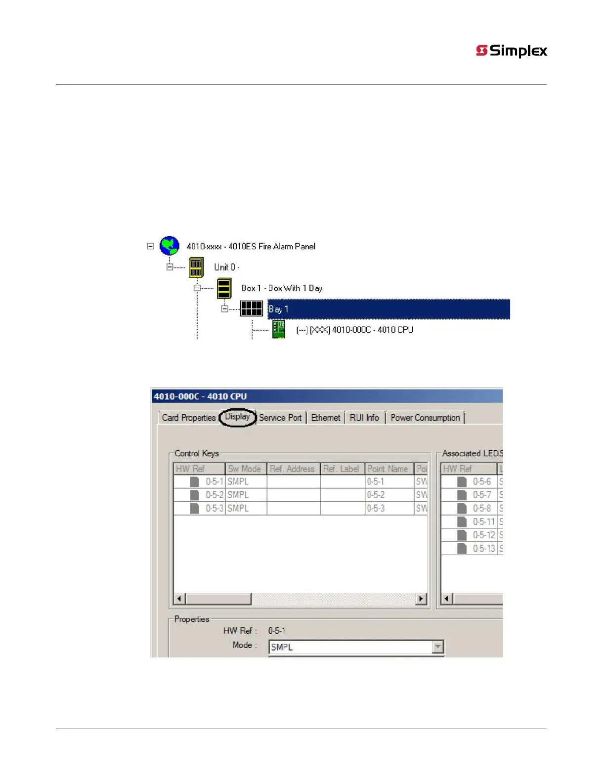
10.1.1 Step 1. Open CPU Card Properties dialog
1. Click on the Hardware tab and expand the Unit 0, Box 1, Bay 1 icons to display the CPU Card. (Click on the + signs to the left of
the Unit 0, Box 1, and Bay 1 icons to expand them.)
Figure 55: Selecting the CPU Card
2. Right-click on the CPU card icon (it is highlighted in the example above) and select Properties. When the CPU card properties
dialog appears, click on the Display tab as shown in the example below.
Figure 56: The Display tab: Display checkbox