page 12 579-1150 Rev M
4010ES IDNAC Fire Alarm System Installation Guide
3.1.1 CPU LEDs
The tables below outline the functions of the LEDs on the CPU card.
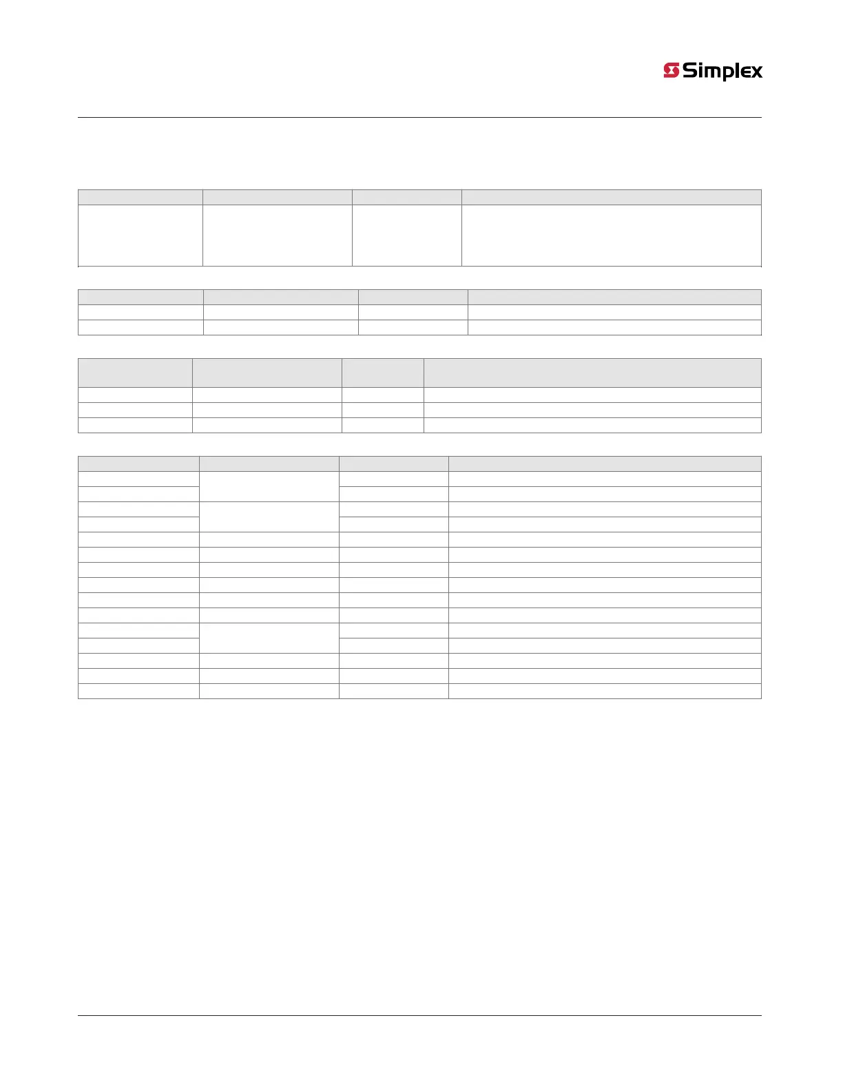
Table 1: Reset LED
Reference designator Silkscreen name Color Status
LED4 RESET Yellow
ON = CPU is in reset
FLASHING = Board is unable to come out of reset. Possibly
corrupt CFIG or board needs to be replaced.
OFF = CPU is running normally
Table 2: Ethernet LEDs
Reference designator Silkscreen name Color Status
LED5 STATUS Green ON = Cable connected
LED6 ACTIVITY Red FLASHING = Ethernet activity
Table 3: RUI trouble LEDs
Reference
designator
Silkscreen name Color Status
LED1 OPEN Yellow ON = Class A fault (open-circuit) or a short
LED2 B SHORT Yellow ON = Short-circuit on the Primary side
LED3 A SHORT Yellow ON = Short-circuit on the Secondary side
Table 4: Front panel LEDs
Reference designator Silkscreen name Color Status
LED11 Red ON = User-definable key A active (Note)
LED12
USER-DEF A
Yellow ON = User-definable key A active (Note)
LED13 Yellow ON = User-definable key B active (Note)
LED14
USER-DEF B
Red ON = User-definable key B active (Note)
LED15 ALARM SILENCED Yellow ON = Alarm silenced
LED16 TRBL Yellow ON = Trouble
LED17 SUPV Yellow ON = Supervisory
LED18 PRI2 Red ON = Priority 2 alarm
LED19 FIRE Red ON = Alarm
LED20 AC POWER Green ON = System power is functioning properly
LED21 Yellow ON = User-definable key C active (Note)
LED22
USER-DEF C
Green ON = User-definable key C active (Note)
LED23 CTRL 1 Yellow ON = Control key 1 active
LED24 CTRL 2 Yellow ON = Control key 2 active
LED25 CTRL 3 Yellow ON = Control key 3 active
Note: Only one LED in each user-definable pair will be on at a time, never both.