page 14 579-1150 Rev M
4010ES IDNAC Fire Alarm System Installation Guide
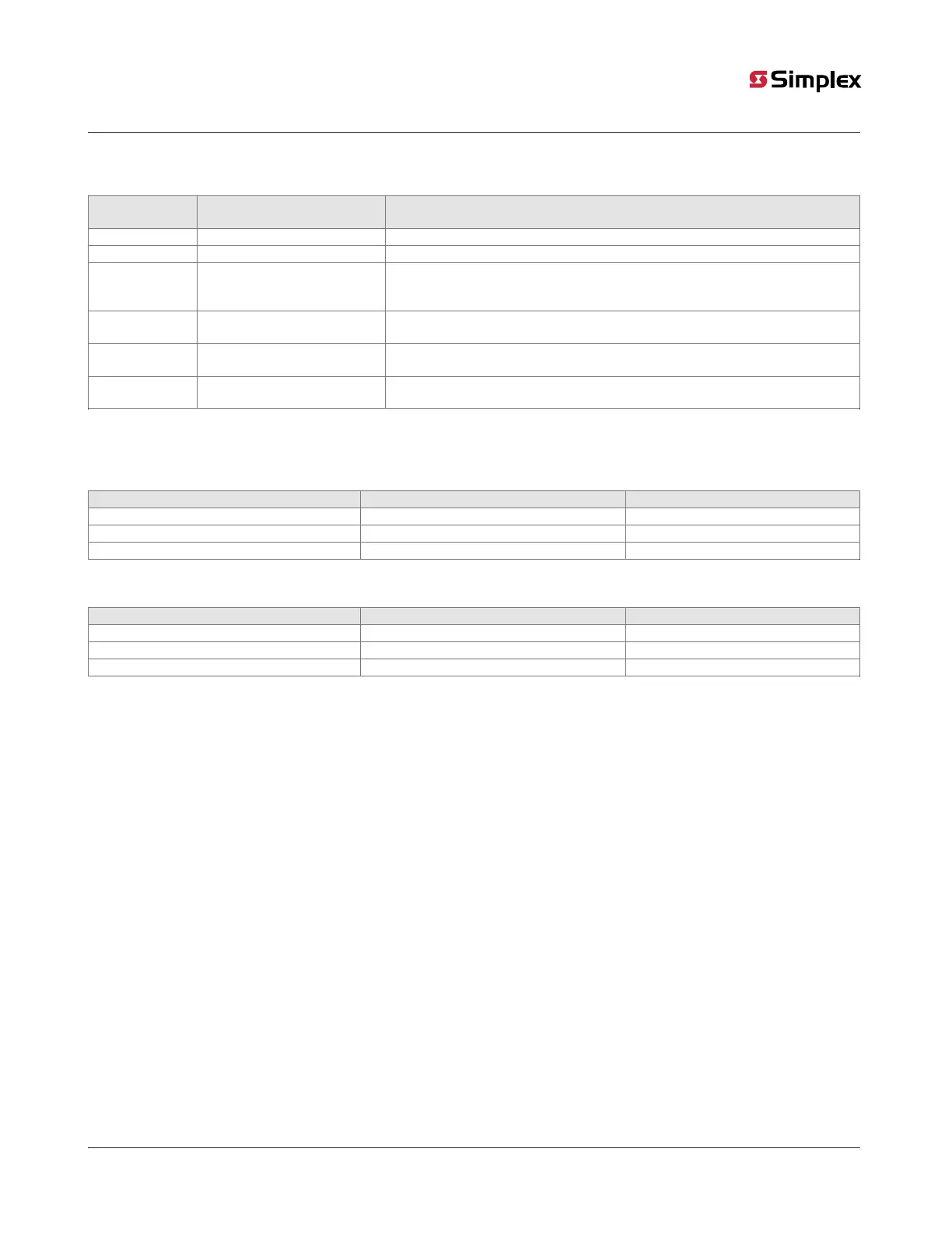
3.1.4 CPU connectors/ports/terminal block
Table 8: Connectors/ports/terminal block
Reference
designator
Silkscreen name Function
P3 COMPACT FLASH Used for alternative job/exec storage.
P8 KEYPAD MEMBRANE Used to communicate user inputs from the keypad membrane to the CPU card.
P9 & P10 24V POWER / INTERNAL COMMS
Used to provide the necessary connections to daisy chain 4100 Comms and 24VDC
card power in an in-out fashion. 24VDC card power originates from the ESS. 4100
Comms originates from the CPU card.
P11 SERIAL SERVICE PORT
Used to connect the CPU card to the Remote Service Gateway. It may also be used
as a service port if the Ethernet Service Port is not available.
J7 ETHERNET SERVICE PORT
Used to connect the panel to a local PC (through the Front Panel Ethernet
connection board or 4010-9914 BNIC or 4010-6310 ES Net NIC).
TB1
RUI A-, RUI A+, SHIELD, RUI B-,
RUI B+
Remote user interface (RUI) used for communication between the CPU and remote
slaves.
3.1.5 CPU card specifications
Table 9 shows the battery current draw for the CPU card.
Table 9: Battery standby (24V)
Configuration Supervisory current draw Alarm current draw
RUI Disabled 124mA 173mA
RUI Enabled - No Load 149mA 198mA
RUI Enabled - Full Load 176mA 225mA
Table 10 shows the maximum draw over the voltage range.
Table 10: Maximum draw over voltage range
Configuration Supervisory current draw Alarm current draw
RUI Disabled 144mA 208mA
RUI Enabled - No Load 167mA 226mA
RUI Enabled - Full Load 186mA 248mA
Note: CPU InfoAlarm supervisory and alarm current draws are both the same as the supervisory current draw.