Simrad AP16 Autopilot
70 20221560E
3.16 JS10 Joystick
Refer to separate installation instructions supplied with the JS10
Joystick.
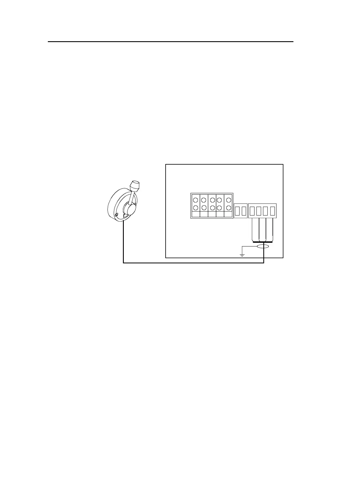
3.17 S35 NFU Lever installation
The unit is mounted to a bulkhead or panel by two screws from
the front. The cable is connected to the junction unit according to
Figure 3-15. Interchange the Port and Stbd wires to the screw
terminals if necessary to make the direction of the lever
movement coincide with the direction of the rudder movement.
TB6
AUTOPILOT COMPUTER
POWER PCB
TB3
TB4
TB5
TB7
S35
STEERING LEVER
TB1 TB2
Lamp
Stbd
Port
Gnd
Brn/Wh
Pnk/Gry
Yel
Grn
NOTE!
Disregard the color code
on the terminal label.
REMOTE
Figure 3-15 S35 connection
The unit is opened by removing the three screws on the back
cover. Inside are two sets of micro-switches, a printed circuit
board with a plug-in terminal and a jumper strap.
3.18 Interfacing
With the AP16 autopilot system there are several possibilities to
connect to other equipment for data collection and exchange:
1. Use SimNet
2. Use SimNet via AT10 Universal SimNet/NMEA Converter
3. Connect to a NMEA2000 network via adapter (drop) cable,
part no. 24005729.
4. The AC10 has a single NMEA0183 input/output port.
5. The AC20 and AC40 have two NMEA0183 input/output ports
and Clock Data interface to Simrad and Furuno radars.