Simrad AP25 Autopilot
52 20222139A
Cable connections
Use only shielded cables, also for the Mains input. Signal cables
should be 0.5 mm
2
(AWG20) twisted pairs.
The mains supply cable should have sufficient wire gauge;
minimum 1,5 mm
2
(AWG14).
Grounding and RFI
The autopilot system has excellent RFI protection. The autopilot
computer should have a proper ground connection to the
hull/bonding system.
Robnet2 cables and other signal cables (Volvo IPS) should not
be run in parallel with other cables carrying RF or high current,
such as VHF and SSB transmitters, battery chargers/ generators,
winches and thrusters.
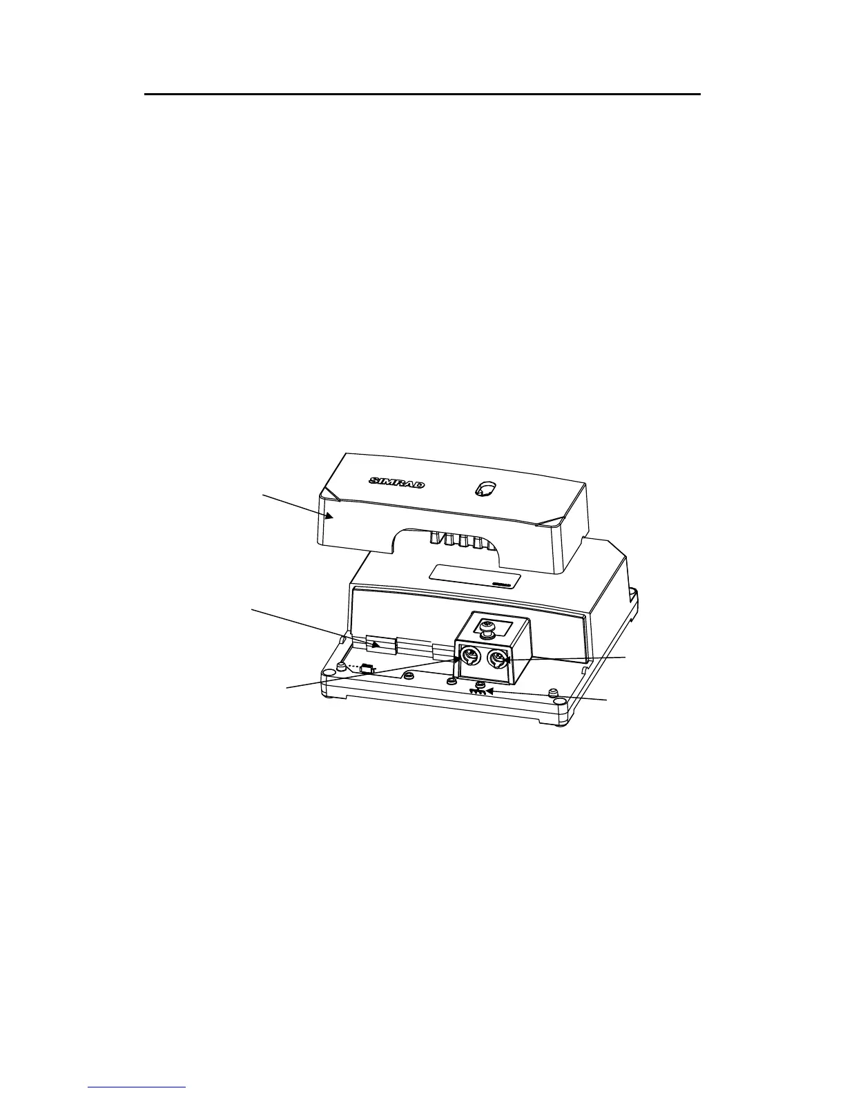
Figure 3-2 AC05 Autopilot Computer
Remove the terminal cover to get access to the plug-in terminals.
Provide sufficient wire length so that the plug-in terminals can
be easily connected/disconnected.
Pull out each terminal before connecting the wires. Remove all
strands before putting on the terminal cover.
Caution ! Do not mix the (blue) Robnet cable with the (black) Volvo IPS
cable.
Ground terminal
Volvo autopilot
interface