Simrad AP25 Autopilot
60 20222139A
3.11 JS10 Joystick
Refer to separate installation instructions supplied with the JS10
Joystick.
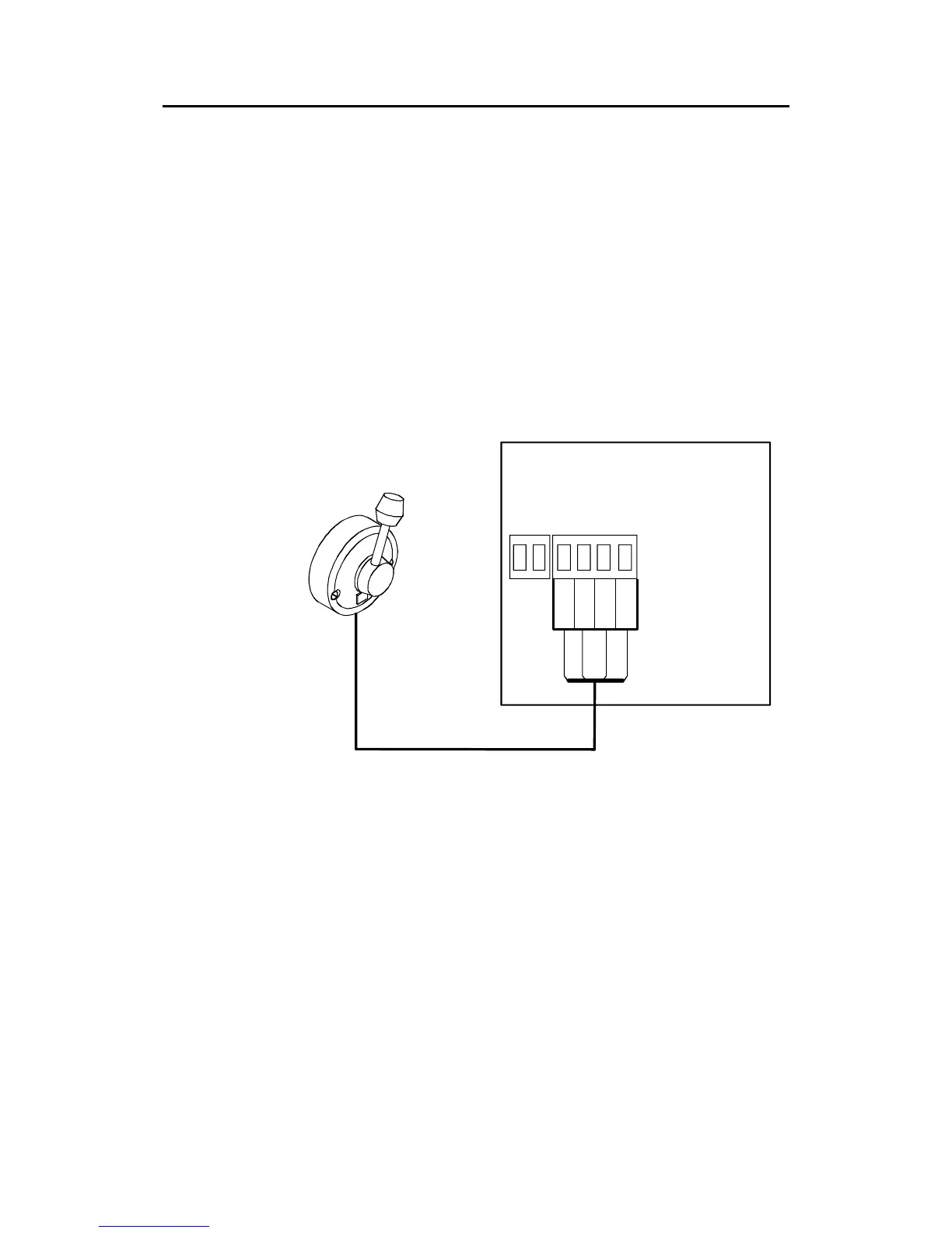
3.12 S35 NFU Lever installation
The unit is mounted to a bulkhead or panel by two screws from
the front. The cable is connected to the autopilot computer
according to Figure 3-11. Interchange the Port and Stbd wires to
the screw terminals if necessary to make the direction of the
lever m
ovement coincide with the direction of the rudder
movement.
S35
STEERING LEVER
TB1
AUTOPILOT COMPUTER
TB2 NFU
GND
PORT
STBD
LAMP
Green
Pnk/Gry
Brn/Wh
Yellow
1
4
Figure 3-11 S35 connection
The unit is opened by removing the three screws on the back
cover. Inside are two sets of micro-switches, a printed circuit
board with a plug-in terminal and a jumper strap.
3.13 Interfacing
With the AP25 autopilot system there are several possibilities to
connect to other equipment for data collection and exchange.
1. Use SimNet
2. Use SimNet via AT10 Universal SimNet/NMEA Converter
3. Connect to a NMEA2000 network via the adapter (drop)
cable, part no. 24005729.