Simrad AP25 Autopilot
66 20222139A
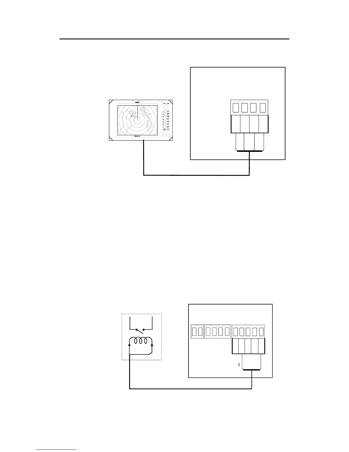
3.15 Radar Clock/Data Heading Output
SIMRAD/ANRITSU
OR
FURUNO
RADAR
AUTOPILOT COMPUTER
TB4 RADAR
CLK L
CLK H
DATA L
DATA H
1
4
Figure 3-17 Radar Clock/Data connection
3.16 IS15 Instrument installation
For installation and operation of the IS15 instruments refer to
separate manuals. For interfacing the IS15, you need the
dedicated AT15 Active Tee as an interface item (page 65, 96).
3.17 External Alarm
The external alarm circuit has an open collector output for an
external alarm relay. The operating voltage for the circuit is an
internal AC05 voltage. Max. load on the alarm voltage is
125 mA.
TB1
AUTOPILOT COMPUTER
TB2 NFU
OUT 1
+12V
+
1
4
TB3
1
5
Figure 3-18 External alarm connection