Simrad AP26 and AP27 Autopilots
64 20222147A
3.11 JS10 Joystick
Refer to separate installation instructions supplied with the JS10
Joystick.
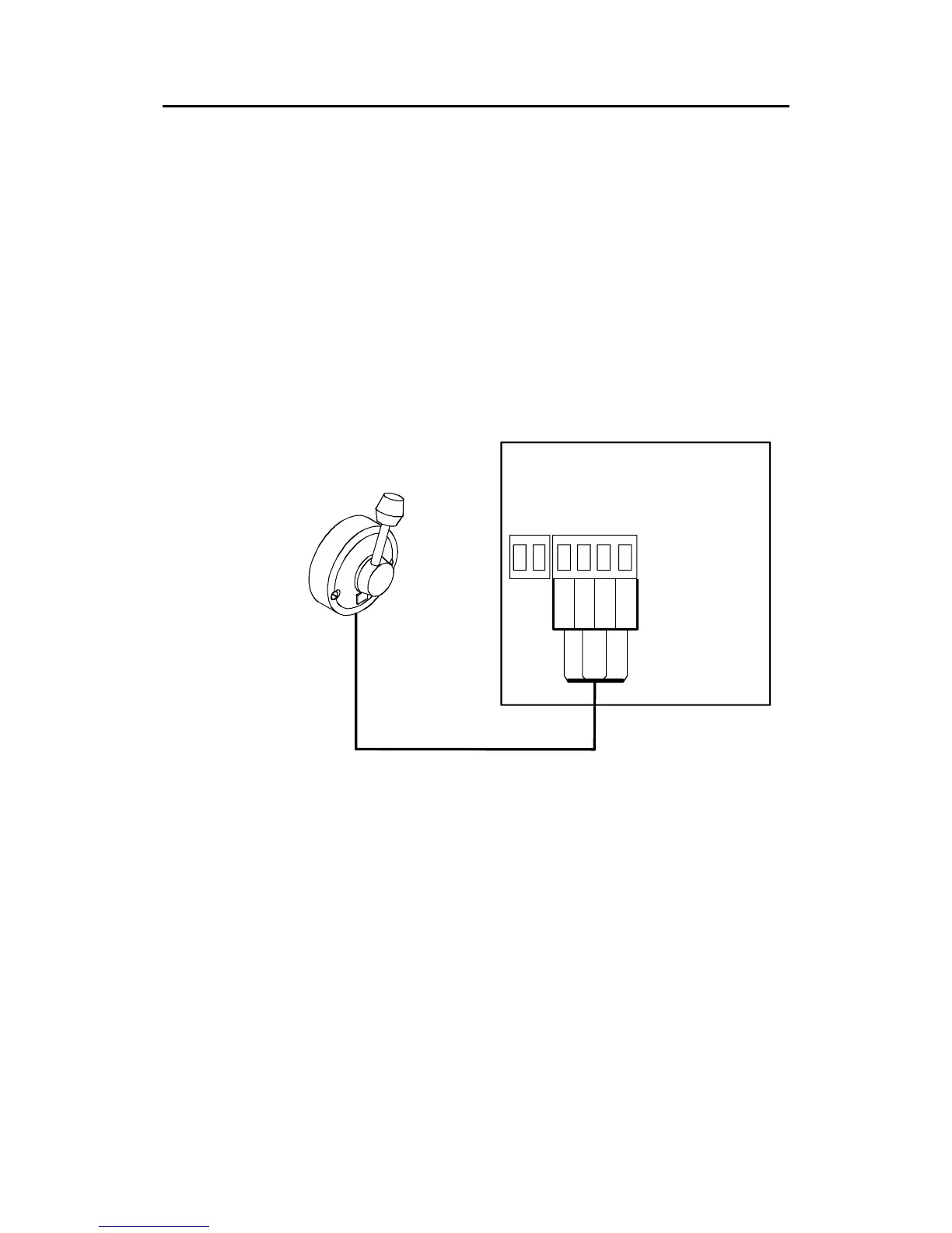
3.12 S35 NFU Lever installation
The unit is mounted to a bulkhead or panel by two screws from
the front. The cable is connected to the autopilot computer
according to Figure 3-11. Interchange the Port and Stbd wires to
the screw terminals if necessary to make the direction of the
lever m
ovement coincide with the direction of the rudder
movement.
S35
STEERING LEVER
TB1
AUTOPILOT COMPUTER
TB2 NFU
GND
PORT
STBD
LAMP
Green
Pnk/Gry
Brn/Wh
Yellow
1
4
Figure 3-11 S35 connection
The unit is opened by removing the three screws on the back
cover. Inside are two sets of micro-switches, a printed circuit
board with a plug-in terminal and a jumper strap.
3.13 Interfacing
With the autopilot system there are several possibilities to
connect to other equipment for data collection and exchange:
1. Use SimNet
2. Use SimNet via AT10 Universal SimNet/NMEA Converter
3. Connect to a NMEA2000 network via the adapter (drop)
cable, part no. 24005729.