FS70 Trawl Sonar System
68 974-24007001/5.0
4.2.12 Connection to Cable Winch/Slip-Rings
The connection between the FS TTM Interface unit and the cable winch/slip-rings should
be made with a 12AWG or heavier, shielded pair cable. The connection to the control unit
is made using the 3-pin MS connector supplied in the TTM module accessory kit. To
minimize noise interference on the cable, the shield of the cable should be attached to the
connector.
NOTES:
1. The shield of the cable between the FS TTM module and the slip-rings should be
connected at the TTM module, but NOT at the slip-rings.
2. Based on experience from previous installations, good results were achieved using a
section of your 3rd wire cable for this connection.
4.2.13 Assembling of the Trawl Unit
Assembling the trawl unit for the first time should be conducted in the wheel house where
the surface unit electronics have been mounted. This will facilitate testing the trawl unit
using the test cable.
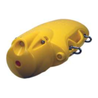
4.2.14 FS 70 Configuration
The FS 70 trawl configurations all consist of an FS 70, 120 kHz or 330 kHz vertical sonar
head with a 200 kHz echo sounder, an FS 70 sensor module is integrated in the trawl sonar
head. The FS 70 polyurethane housing includes mounting and assembling hardware and a
strain relief. The trawl unit also contains a catch receiver unit and the echo sounder
transducer. Assembly of the unit involves correctly locating the sonar head, attaching the
strain relief to the trawl cable, proper routing and connection of the cable to the sonar head
and bolting the polyurethane housing together. This section describes the connection and
location of the sonar head, echo sounder transducer and catch receive transducer. Final
assembly is illustrated in the “Drawings” section.
A locating block positioned at the end of the housing or a guide bracket is used to prevent the
sonar head from rotating. Only one guide block is required and it can be placed into the
positioning hole of the bottom half of the trawl unit housing as shown in the assembly
drawing in Chapter 6.
NOTE: Dow Corning “#55” grease must be applied to all mating surfaces of
underwater connectors to insure proper sealing. Sufficient grease should be applied so
that excess squeezes out with any air when the connectors are mated. RTV or any
other sealant must NOT be used, and when tightening the locking sleeves, do NOT use
a wrench or pliers!